Aerosol can

A technology of spray cans and spray heads, which is applied in the direction of spraying devices, liquid distribution, application, etc., can solve problems such as sudden spraying, and achieve the effect of high fixed torque

Inactive Publication Date: 2006-03-22
THOMAS SA
View PDF1 Cites 0 Cited by
  • Summary
  • Abstract
  • Description
  • Claims
  • Application Information

AI Technical Summary

Problems solved by technology

However this is often forgotten and can cause bursts of jetting afterwards if not careful

Method used


Image

  • Aerosol can
  • Aerosol can
  • Aerosol can

Examples


Embodiment Construction

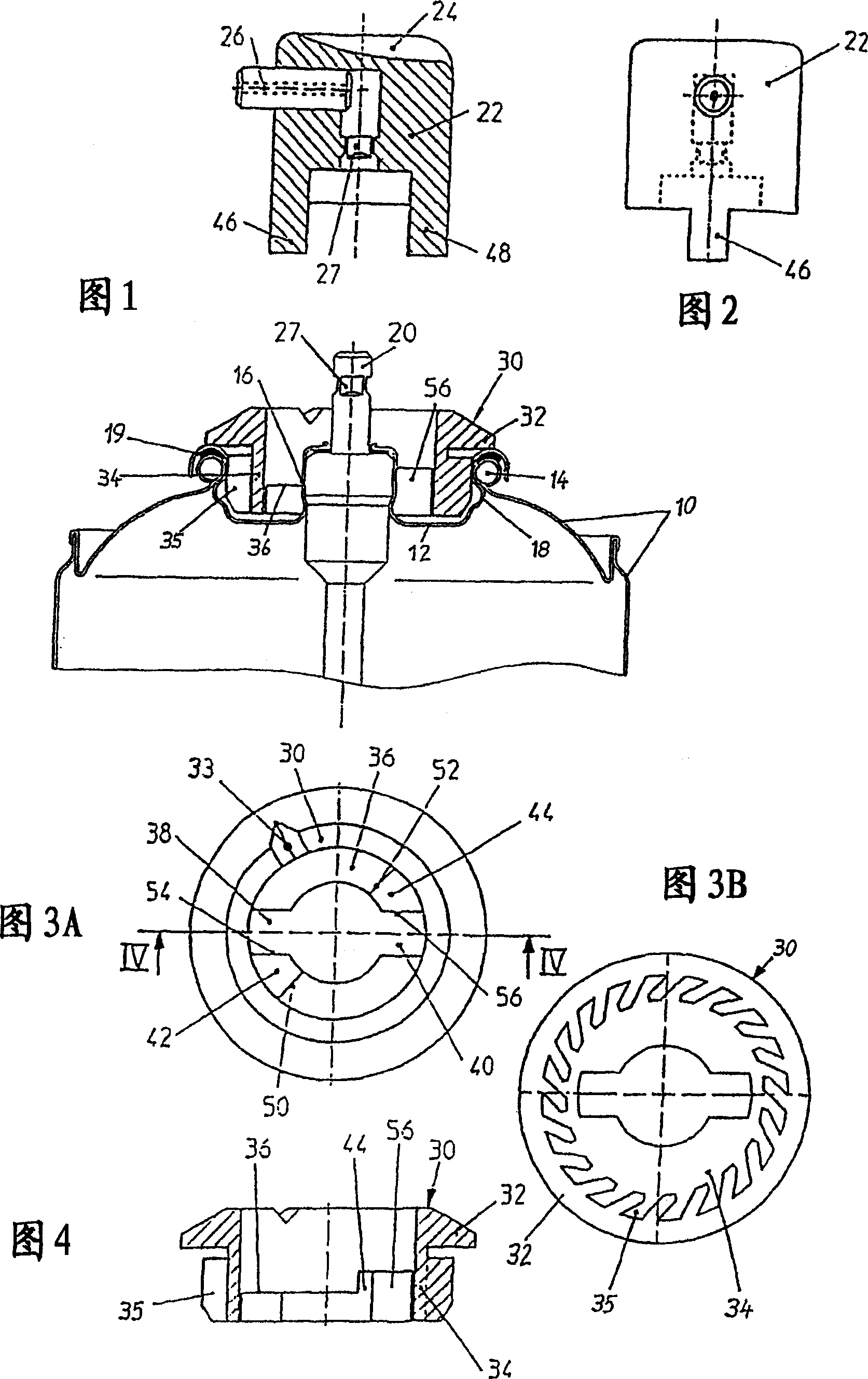
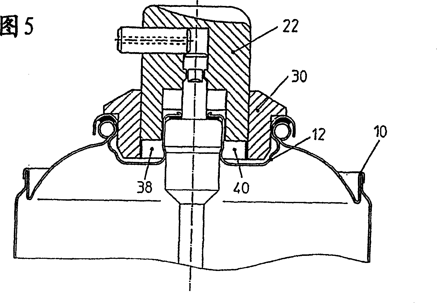
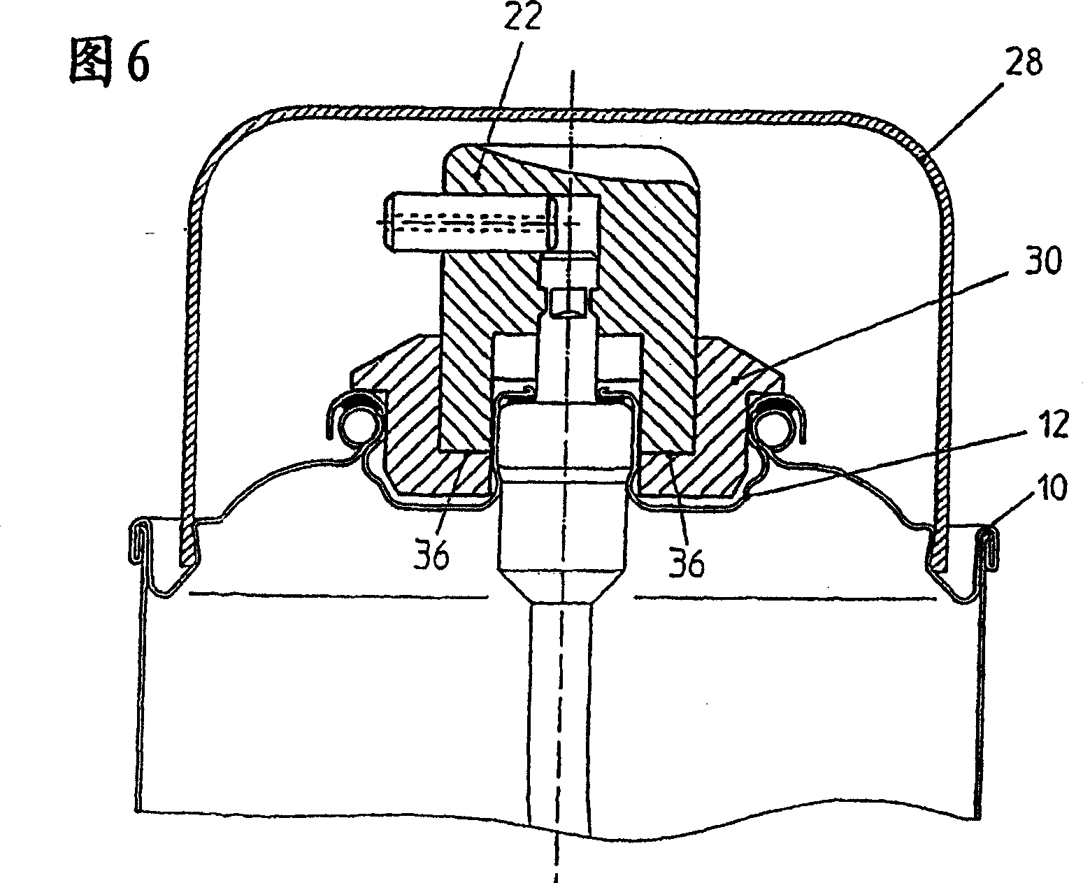
[0025] Shown in Fig. 1 is the top of an aerosol can, and its tank body is represented with 10, and its valve disc is represented with 12. For the invention it is immaterial whether the tank body 10 is made of tin in multiple pieces or in a single piece of aluminum alloy. The container opening provided with the beaded edge 14 in both cases is sealed by the corresponding valve disk 12 fastened thereon, which is formed in a common manner with a valve cover 16 in the region of its center and radially outside it. The region of the hood is formed with a flange 18 extending concentrically around the shroud. The valve housing 16 contains part of the spray valve, while the flange 18 is secured by clamping to the beaded edge 14 of the tank 10, with a sealing ring 19 or laminated sealing material achieving a tight seal.

[0026] Projecting upwards from the valve housing 16 is a push rod 20 which on the one hand serves as an actuating plunger for the spray valve in the housing 16 and on ...


PUM


Abstract

The spray can has a valve disk (12) with a valve, which valve disk is formed with a valve dome (16) and a fastening collar (18) surrounding it at a radial intermediate distance. The valve is actuated by pushing down a rotatable spray head (22) seated on a tappet (20). For obtaining turning stops for an actuating position and a closing position without taking special steps on the valve disk (12) or can body (10), it is provided that a stop ring (30) is arranged, fixed against relative rotation, in the annular space between the valve dome (16) and the collar (18). For being adaptable to materials of different thickness of the valve disk (12), it is formed with lamellas (35) at the outer circumference, is pushed with press fit into the collar (18) and has a cam track (36) with at least one recess extending along the circumference. The spray head (22) is formed or connected with at least one cam (46, 48). It acts together with turning stop faces (56) on the stop ring (30). Acting together with the cam track (36), it permits the spray head (22) to be pushed down only if the cam (46) is located above the recess.

Description

technical field [0001] The invention relates to an aerosol can comprising a valve disc with a valve shaped as a valve cover and a flange surrounding the valve cover at radial distances and secured by clamping to the beaded edge of the can body ; also includes a rotatable spray head, which can be mounted on a push rod protruding upward from the valve housing, which can move axially to control the valve, and must be depressed together with it from the closed position against the force of the spring into the spray position , wherein a baffle ring is press-fitted into the gap between the valve cover and the flange in an anti-rotational manner, and the baffle ring is formed with a protruding rail surface ( Nockenbahn), on which one or more projections (Nocken) can be moved by a small distance or slidingly during the rotation of the spray head to the closed position, while at least one stop connected to it can be moved between two Rotate back and forth between two stop surfaces ext...

Claims


Application Information

Patent Timeline
Patent Type & Authority Patents(China)
IPC IPC(8): B65D83/16B65D83/34B05B11/00B21D51/26B65D83/14B65D83/36
CPCB65D83/40B65D83/205B65D83/22B65D2215/04
Inventor 海因茨·施奈德
Owner THOMAS SA
Why Eureka
Try Eureka