Yarn feeding device

A technology for feeding device and yarn, which is applied in the field of yarn feeding device to achieve the effect of convenient adjustment and quick adjustment

Inactive Publication Date: 2006-06-28
IROPA AG (CH)
View PDF1 Cites 0 Cited by
  • Summary
  • Abstract
  • Description
  • Claims
  • Application Information

AI Technical Summary

Problems solved by technology

However, the above-mentioned reversal only allows the drive shaft to rotate in one direction of rotation, that is, in the winding direction.
For this reason, it is not possible to adjust the yarn spacing by simply turning the drive shaft in the locked direction of rotation by means of the winding element.

Method used


Image

  • Yarn feeding device
  • Yarn feeding device

Examples


Embodiment Construction

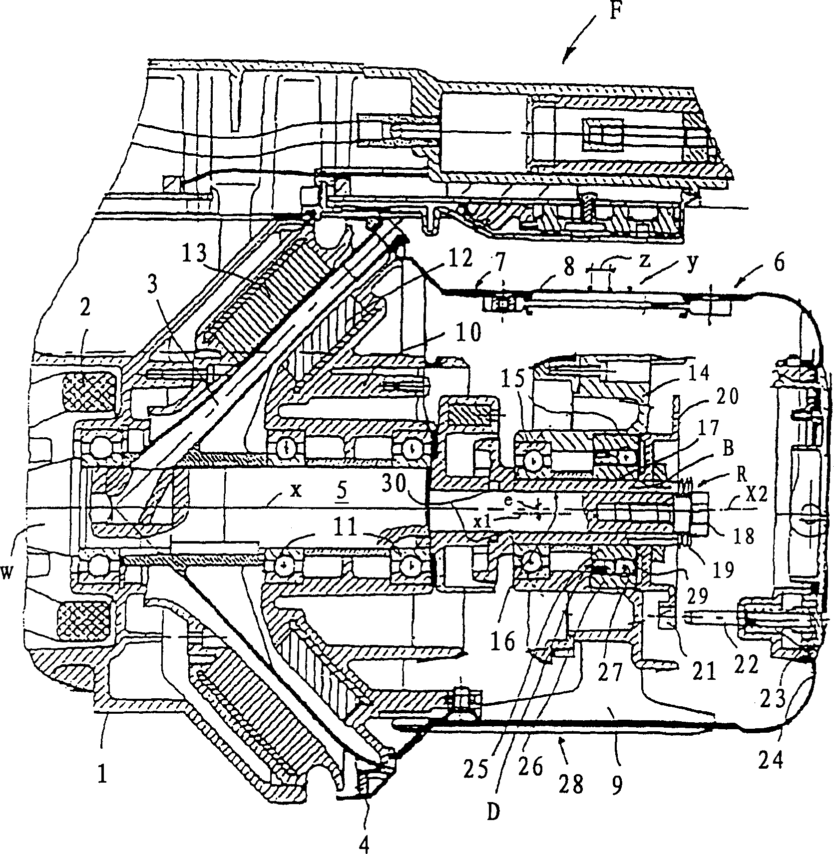
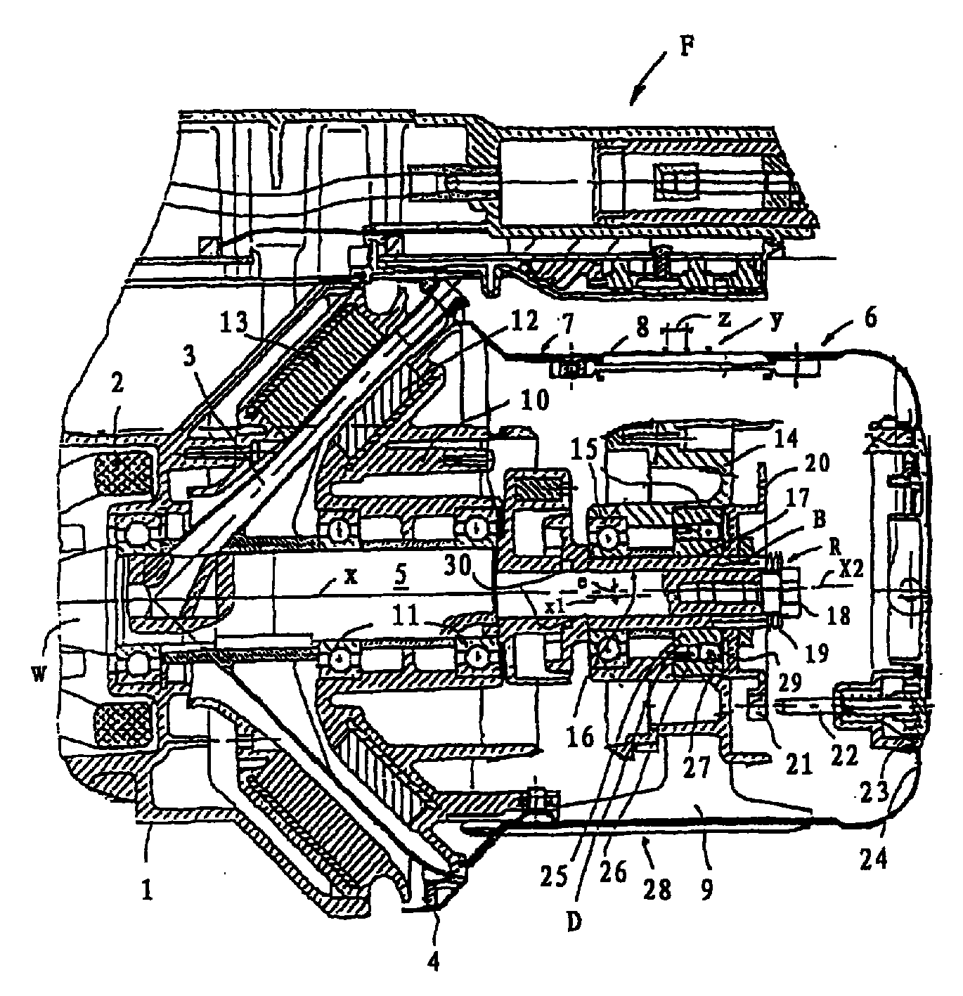
[0021] figure 1 The yarn feeding device F in has a motor housing 1 which contains a motor 2 which drives a drive shaft W so that it rotates about an axis X in a selected direction of rotation. A winding element 3 , for example a winding tube, is arranged on the drive shaft W, terminates outside the motor housing 1 and extends from the hollow drive shaft W obliquely outwards. Such a winding element is arranged in a so-called winding disk 4, which is arranged on the drive shaft W and is located between the motor housing 1 and a storage drum 6 which passes through the drive shaft W. W is supported on the motor case 1 . The drive shaft W serves as a carrier for the storage drum 6 and has a coaxial extension 5 for this purpose.

[0022] The storage drum 6 is composed of two intermeshing rod-cage cylinders, that is, one is a support rod-cage cylinder 7 with several axial rods 8 spaced apart in the circumferential direction, and the other is a support rod-cage cylinder 7 with sever...


PUM


Abstract

The invention relates to a yarn feeding device (F) with a stationary storage drum and an adjustable yarn pitch. The yarn feeding device comprises a motor housing, a drive shaft of a reeling element (3) and a storage drum (6). Said storage drum consists of meshing finger-shaped cages (7, 8 and 28). The finger-shaped advance cage (28) has an advance bearing (15) that is eccentric and sloped with respect to the drive shaft (W). A recoil break (D) for the take-up element (3) is mounted in said advance cage. Said recoil brake (D) is furthermore interposed between the finger-shaped advance cage (28) and the drive shaft (W).

Description

(1) Technical field [0001] The present invention relates to yarn feeding devices. (2) Background technology [0002] The yarn feeding device disclosed in the prior art, for example WO / A-99 / 14149, has an adjustable yarn spacing during operation and has a reverse stop for the winding element. Such yarn feeding devices are mainly used for processing specialized yarn materials, for example supplying weft yarns when weaving filter or guide fabric webs used in paper or board production. Due to the elasticity or stiffness of the yarn material, or due to certain mechanical conditions, when the winding element is stopped, the winding element has a tendency to reverse direction against the winding direction. This has the potential to cause loops or kinks in the yarn, or cause overlap between the yarns wound on the storage drum, ultimately causing the operation to fail. A counter-rotation brake is provided between the motor housing and the drive shaft or in the support bearing of the...

Claims


Application Information

Patent Timeline
Patent Type & Authority Patents(China)
IPC IPC(8): B65H51/22D03D47/34D03D47/36D04B15/48G05G5/00
CPCG05G5/00D03D47/34D03D47/361
Inventor P·约瑟夫松A·本特松
Owner IROPA AG (CH)
Why Eureka
Try Eureka