Unit for sealing end surface of 3D helical flute with double helix angles
A technology of end face sealing and spiral groove, which is applied in the direction of engine sealing, engine components, mechanical equipment, etc., and can solve problems such as insufficient fluid film stiffness, insufficient fluid film thickness, and unstable performance of sealing devices
- Summary
- Abstract
- Description
- Claims
- Application Information
AI Technical Summary
Problems solved by technology
Method used
Image
Examples
Embodiment 1
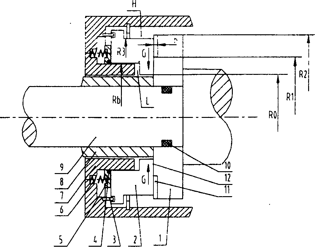
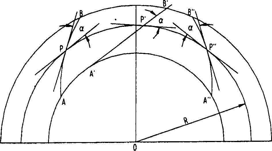
[0077] Example 1: Please refer to figure 1 , image 3 , Figure 4 and Figure 5 .
[0078] figure 1 It is a cross-sectional view of a double-helix-angle three-dimensional helical groove end face sealing device with helical grooves arranged on a rotating ring. The sealing device includes a rotating ring 1 , a stationary ring 2 , an anti-rotation pin 3 , a secondary sealing ring 4 , a push ring 5 , a spring 6 , a housing 7 , a shaft sleeve 8 , a shaft 9 and a static sealing ring 10 .
[0079] The sealing end surface of the rotating ring 1 and the sealing end surface of the stationary ring 2 are attached to each other, the former can rotate relative to the latter, and the bonding surface of the two is the sealing end surface. In this embodiment, the outer side of the sealing end surface is the high pressure side, that is, the upstream H, and the inner side of the sealing end surface is the low pressure side, that is, the downstream. A spiral groove 11 is provided on the sea...
Embodiment 2
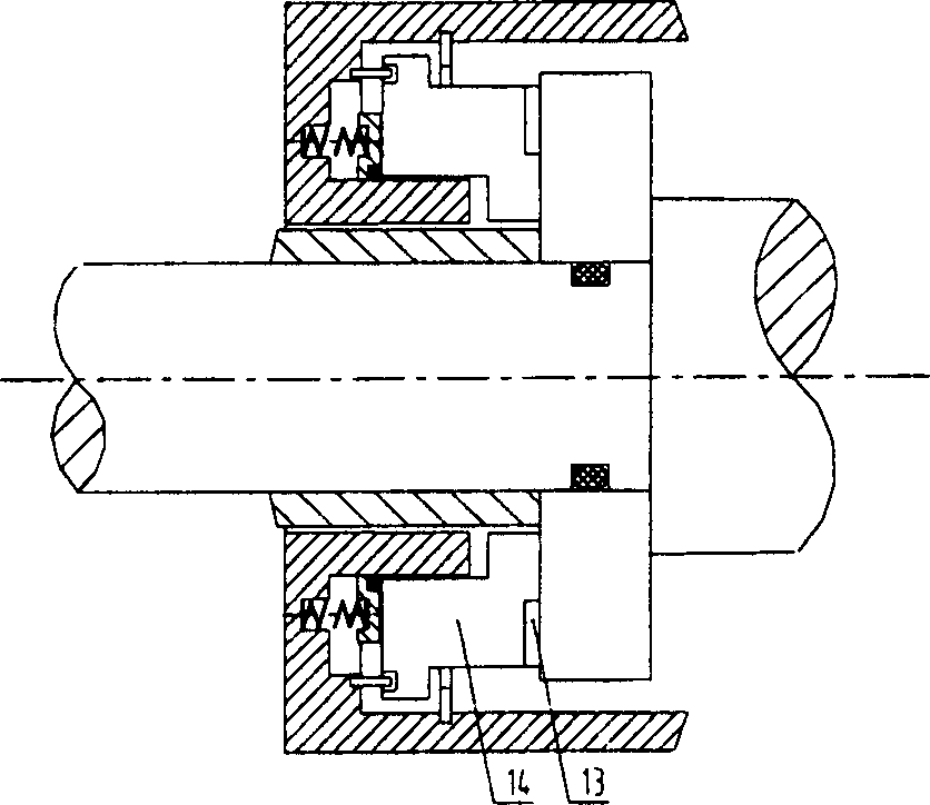
[0087] Embodiment 2: The only difference with the structure of Embodiment 1 is that the spiral groove 13 is set on the sealing end surface of the stationary ring 14, please refer to figure 2 . In addition, the spiral groove can also be provided on the sealing end faces of the rotating ring and the stationary ring at the same time (illustration omitted).
Embodiment 3
[0088] Example 3: Please refer to Figure 6 , Figure 8 and Figure 9 .
[0089] The difference from the structure of Embodiment 1 is that the inner side of the sealing end surface in this embodiment is the high pressure side, i.e. upstream H', and the outer side is the low pressure side, i.e. downstream L'. A spiral groove 16 is provided on the sealing end face of the rotary ring 15 . At a given rotation, the helical groove pumps sealing fluid from upstream to downstream in the direction of arrow G'. In addition, there is a flat annular zone 17 inside the spiral groove, that is, at R 4 with R 5 The ring belt between them plays the role of throttling and parking seal, which can be called a sealing dam, please refer to Figure 6 .
[0090] Figure 8 Indicates the shape and position of the spiral groove on the sealing end face. In this figure the effective radial height of the helical groove is (R 5 -R 7 ). Figure 8 and Figure 9 The double-dotted line in the figur...
PUM
 Abstract
Description
Claims
Application Information
 - R&D
- Intellectual Property
- Life Sciences
- Materials
- Tech Scout
- Unparalleled Data Quality
- Higher Quality Content
- 60% Fewer Hallucinations
Browse by: Latest US Patents, China's latest patents, Technical Efficacy Thesaurus, Application Domain, Technology Topic, Popular Technical Reports.
© 2025 PatSnap. All rights reserved.Legal|Privacy policy|Modern Slavery Act Transparency Statement|Sitemap|About US| Contact US: help@patsnap.com


