Luminous container for high voltage discharge lamp

A technology for high-pressure discharge lamps and containers, which is applied to parts of high-pressure discharge lamps and gas discharge lamps, and can solve problems such as unreasonable and complicated steps

Inactive Publication Date: 2006-09-06
NGK INSULATORS LTD
View PDF0 Cites 0 Cited by
  • Summary
  • Abstract
  • Description
  • Claims
  • Application Information

AI Technical Summary

Problems solved by technology

Although the surface roughness of the inner surface of the light-emitting container surface can be controlled by grinding, the steps are complicated, so it is not reasonable

Method used


Image

  • Luminous container for high voltage discharge lamp
  • Luminous container for high voltage discharge lamp
  • Luminous container for high voltage discharge lamp

Examples


Embodiment Construction

[0018] Embodiments embodying the present invention will be described below with reference to the drawings.

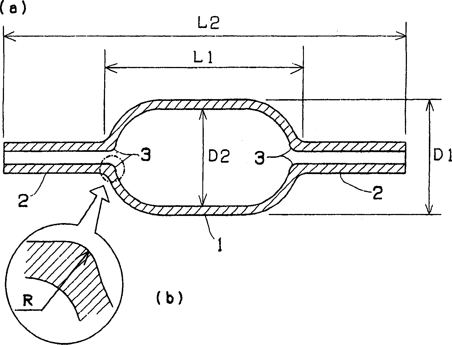
[0019] figure 1 It is a cross-sectional explanatory view showing one embodiment of a light-emitting container for a high-pressure discharge lamp according to the present invention. It has a case 1 having an enlarged diameter and an approximately elliptical shape forming a discharge space in the center. Small diameter capillary part 2. A rod-shaped current conductor (not shown) provided with a discharge electrode is inserted into the tip of the capillary portion 2, and the conductor is sealed and fixed.

[0020] The luminescent vessel is molded by adding alumina as a main component, adding, for example, MgO to the filler, and is formed so as to have translucency after sintering. As an example showing the dimensions of each part, the outer diameter D1 of the casing 1 is 14.8 mm, the inner diameter D2 is 13.0 mm, the length L1 is 25.5 mm, and the total length L2 of the ...


PUM

PropertyMeasurementUnit
surface roughnessaaaaaaaaaa
lengthaaaaaaaaaa
lengthaaaaaaaaaa

Abstract

Disclosed is a light emitting vessel for a high pressure discharge lamp for reducing a light color change in the high pressure discharge lamp using the light emitting vessel by integrally molding an electrode inserting part and at least an end part of a body part, and capable of lengthening the service life. The almost elliptic body part for forming a discharge space, and a capillary part for inserting and fixing a discharge electrode projected outward so as to be mutually opposed from both ends of the body part are integrally molded, and are formed by sintering so as to have light transmissivity by using alumina as a main component, and a boundary end part between the body part being a discharge space corner part and the capillary part is formed by imparting a radius of curvature R of 1.0 mm.

Description

technical field [0001] The present invention relates to a light-emitting container made of light-transmitting ceramics used in high-pressure discharge lamps such as high-pressure sodium lamps and metal halide lamps. A light-emitting container for a high-pressure discharge lamp formed by integral molding. Background technique [0002] A discharge lamp using a light-emitting container made of translucent ceramics in which the discharge space is formed by expanding the diameter of the central portion into an approximately elliptical shape is advantageous in terms of lamp efficiency, and is therefore particularly used in applications where efficiency is important. This luminous container has in the center such as Figure 5 In the shown structure, an approximately elliptical casing 10 forming a discharge space is integrally molded at both ends in the longitudinal direction in opposite directions to form capillaries 11 as electrode insertion portions. After sealing the luminescen...

Claims


Application Information

Patent Timeline
Patent Type & Authority Patents(China)
IPC IPC(8): H01J61/30H01J61/88C04B35/115
CPCC04B35/115H01J61/30
Inventor 宫泽杉夫
Owner NGK INSULATORS LTD
Why Eureka
Try Eureka