Base station device and transmission method

A transmission method and base station technology, which are applied in the direction of selection device, antenna support/installation device, space transmission diversity, etc., and can solve the problems that the wireless part cannot be suppressed from amplifying the dynamic range, the heat generation is large, and the transmission power of the antenna cannot be reduced.

Inactive Publication Date: 2000-11-29
GK BRIDGE 1
View PDF0 Cites 2 Cited by
  • Summary
  • Abstract
  • Description
  • Claims
  • Application Information

AI Technical Summary

Problems solved by technology

[0009] However, in the conventional base station apparatus described above, since a plurality of non-directionally transmitted signals are synthesized and transmitted from one antenna, the transmission power in the antenna cannot be reduced.
Therefore, there is a problem that the dynamic range during the amplification operation of the wireless part cannot be suppressed, and a large amplifier with a large heat generation must be used.

Method used


Image

  • Base station device and transmission method
  • Base station device and transmission method
  • Base station device and transmission method

Examples


Embodiment 1

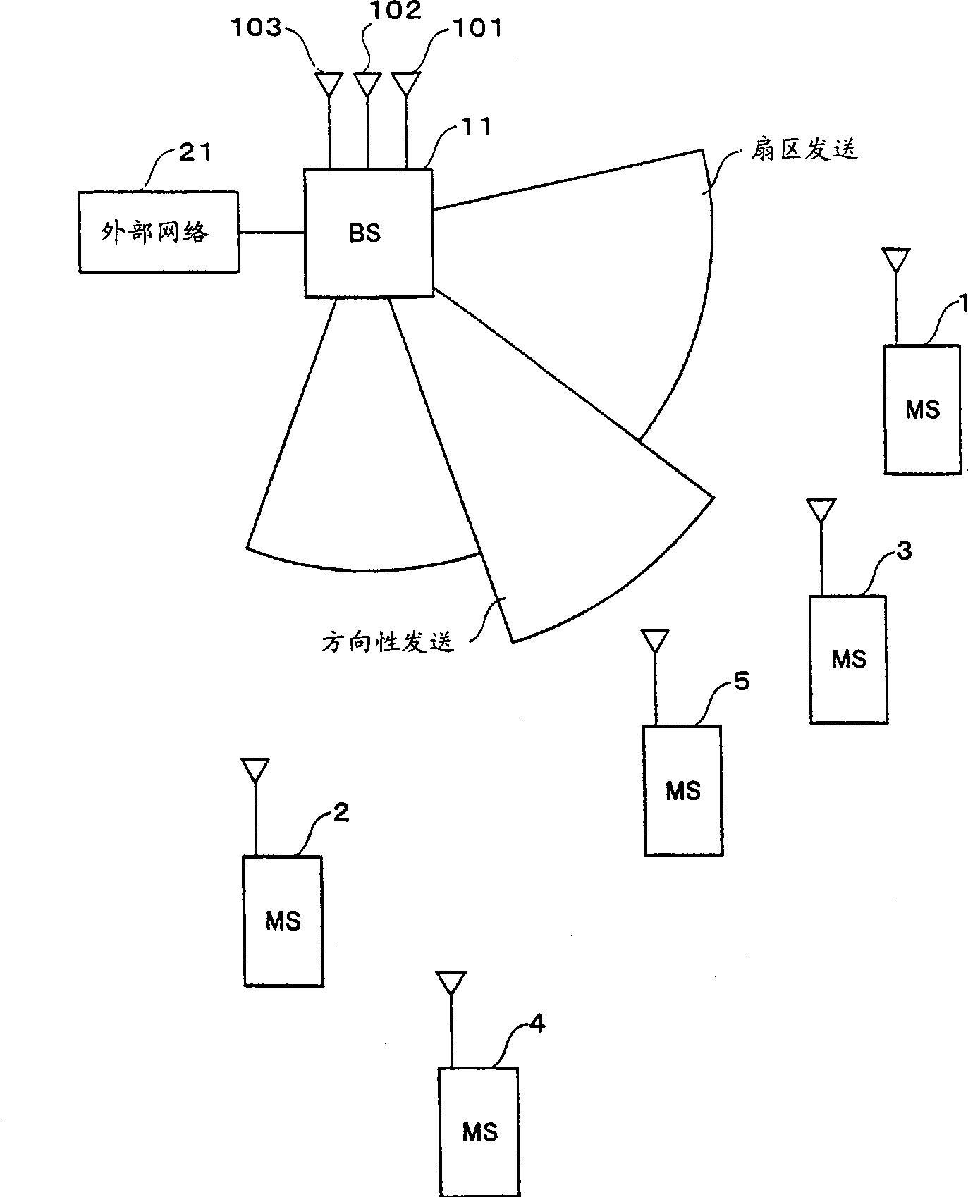
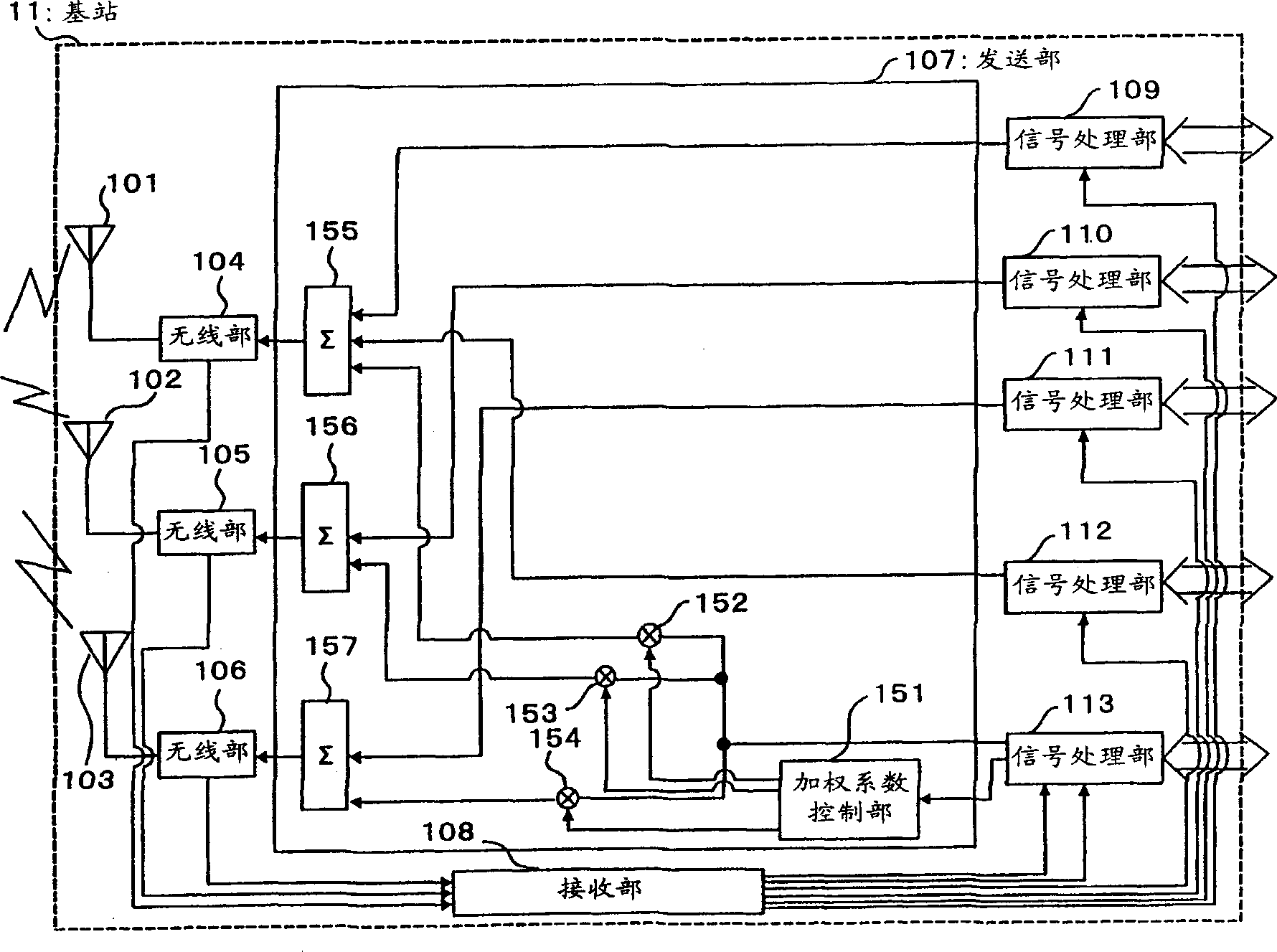
[0021] figure 2 It is a block diagram showing the configuration of the base station apparatus of the first embodiment. figure 2 The shown base station apparatus 11 mainly includes: three antennas 101 , 102 , 103 ; wireless units 104 , 105 , 106 ; transmitting unit 107 ; receiving unit 108 ; The transmission unit 107 has: a weighting factor control unit 151 ; multiplication circuits 152 , 153 , and 154 ; and synthesis circuits 155 , 156 , and 157 .

[0022] Wireless unit 104 converts the high-frequency signal received by antenna 101 into a baseband signal and outputs it to receiving unit 108 , and converts the baseband signal input from synthesis circuit 155 into a high-frequency signal and wirelessly transmits it from antenna 101 . Wireless unit 105 converts a high-frequency signal received by antenna 102 into a baseband signal and outputs it to receiving unit 108 , and converts a baseband signal input from synthesis circuit 156 into a high-frequency signal and wirelessly t...

Embodiment 2

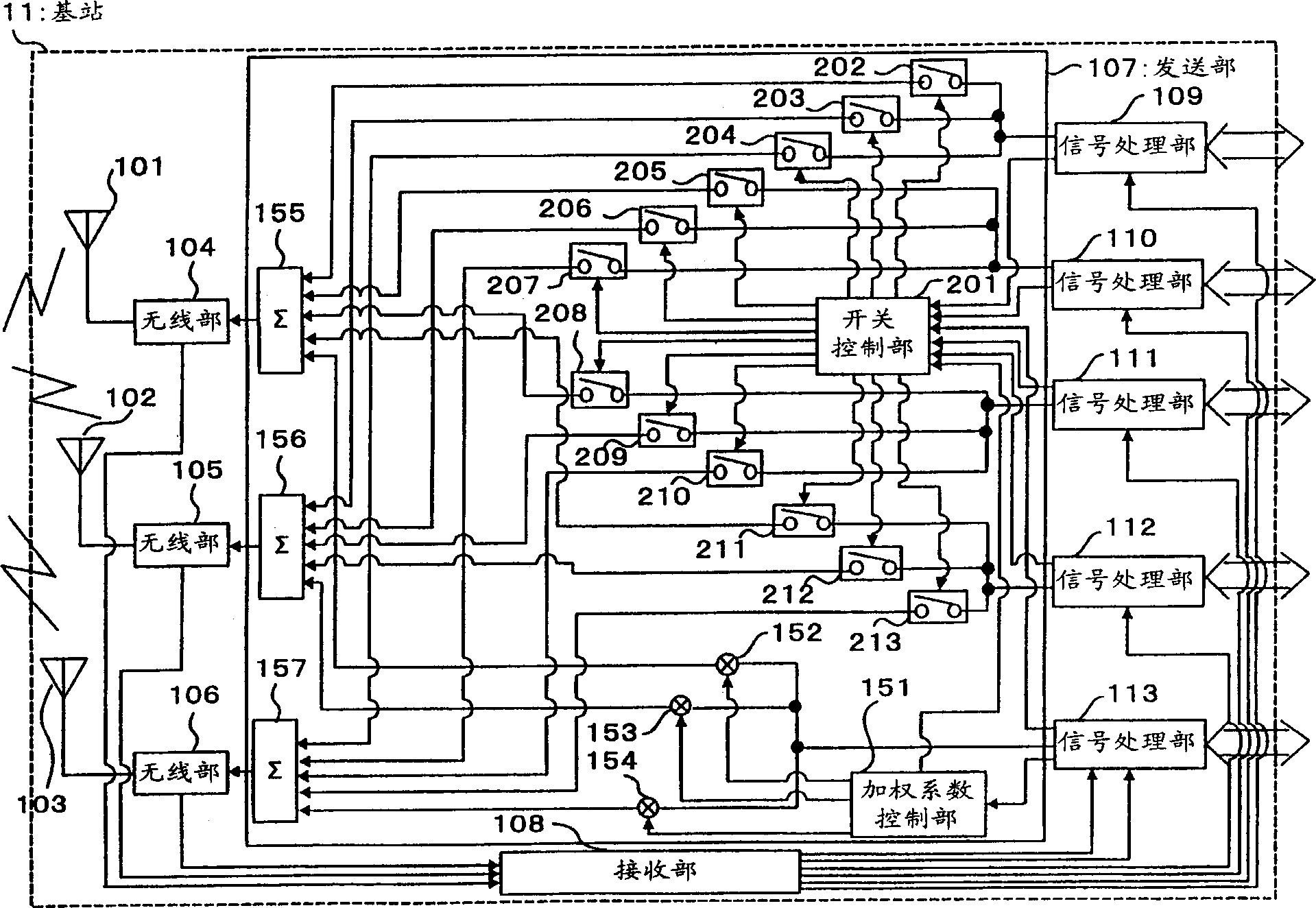
[0043] image 3 It is a block diagram showing the structure of the base station apparatus of the second embodiment. exist image 3 The base station device shown, pair with figure 2 The same parts of the shown base station unit are appended with figure 2 The same reference numerals are used, and descriptions thereof are omitted.

[0044] image 3 The base station unit shown is used in figure 2 A structure in which a switch control unit 201 and connection switches 202 to 213 are added to the base station apparatus.

[0045] The switch control unit 201 controls each connection switch so that the transmission power of each antenna becomes uniform based on the transmission power to each terminal device input from each signal processing unit and the weighting coefficient input from the weighting coefficient 151 . The connection switches 202 to 213 are turned on or off under the control of the switch control unit 201 .

[0046] Hereinafter, as an example, the control of the...


PUM


Abstract

Signals to be subject to variable directional transmission are multiplied by weighting factors for individual antennas (101 to 103) at a multiplier (152) for outputting to synthesis circuits (155 to 157) respectively, while signals not subject to variable directional transmission are output to any one of the synthesis circuits (155 to 157) respectively. A signal input to a synthesis circuit (155) is synthesized, radio-modulated at a radio unit (104) and transmitted from an antenna (101). Similarly, a signal input to a synthesis circuit (156) is synthesized, radio-modulated at a radio unit (106) and transmitted from an antenna (102), and a signal input to a synthesis circuit (157) is synthesized, radio-modulated at a radio unit (106) and transmitted from an antenna (103). Thereby, it is possible to dispersedly transmit signals not subject to variable directional transmission from individual antennas to reduce a transmission power and the size of a device when variable directional transmission is performed on part of terminal devices only.

Description

technical field [0001] The present invention relates to a base station device and a transmission method used in a digital wireless communication system that performs directional transmission through an adaptive array antenna in a downlink. Background technique [0002] Digital wireless communication systems such as mobile phones and automobile phones employ a cellular system in which a communication area is divided into cells, one base station is placed in each cell, and a plurality of terminal devices simultaneously communicate with the base station. In recent years, due to the rapid spread of the cellular system and the rapid increase of system users, increasing the channel capacity in one cell has become an important issue. [0003] As a technique for increasing the channel capacity, there is the self-adaptive technology described in "Digitar Mobile Communications のたぁの Waveform Equalization Technology (Waveform Equalization Technology for Digital Mobile Communications)" (...

Claims


Application Information

Patent Timeline
Patent Type & Authority Applications(China)
IPC IPC(8): H01Q1/24H01Q3/26H01Q3/30H04B1/04H04B7/06H04B7/10H04B7/26H04W16/28H04W88/08H04W88/14
CPCH01Q1/246H01Q3/2605H01Q3/26H01Q3/30H04B7/0617Y02D30/70H04B7/155H04W88/08
Inventor 井出美奈子平松胜彦
Owner GK BRIDGE 1
Why Eureka
Try Eureka