Micro-transfusion core made of plastics and transfusion tube for mounting said transfusion core
A drip, plastic technology used in flow control, non-electric variable control, devices introduced into the body, etc.
- Summary
- Abstract
- Description
- Claims
- Application Information
AI Technical Summary
Problems solved by technology
Method used
Image
Examples
Embodiment 1
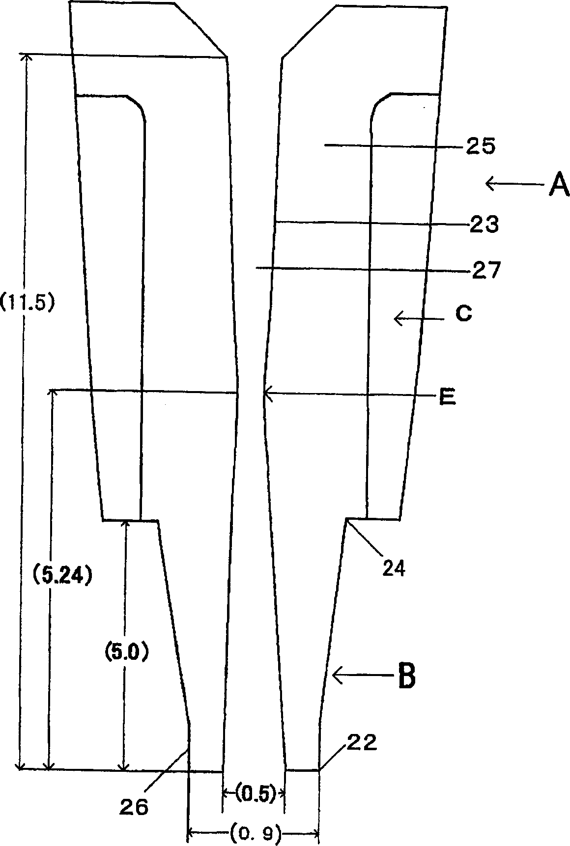
[0024] Embodiment 1——The outside of the wall portion 25 of the drip core part is provided with several ribs C, and the shape is gradually reduced in diameter from top to bottom. Due to the formation of the aforementioned several ribs C, it should have a good separation from the molding die. come out as well. Furthermore, the shape of the wall surface of the inner cavity is to gradually expand the diameter at the upper and lower ends at the middle part E of the inner cavity. The inner diameter of the middle part E of the inner cavity is smaller than the inner diameter of other parts. The wall surface forms a curved portion with the middle part of the cavity as the top, and the radius R of the curved portion is about 560 to 840 mm, preferably about 700 mm. Furthermore, the shape of the outer wall surface 26 near the opening of the needle-tubular plastic top end B is based on figure 2 The vertical shape shown is as well. That is, until the opening of the needle-shaped plastic ...
Embodiment 2
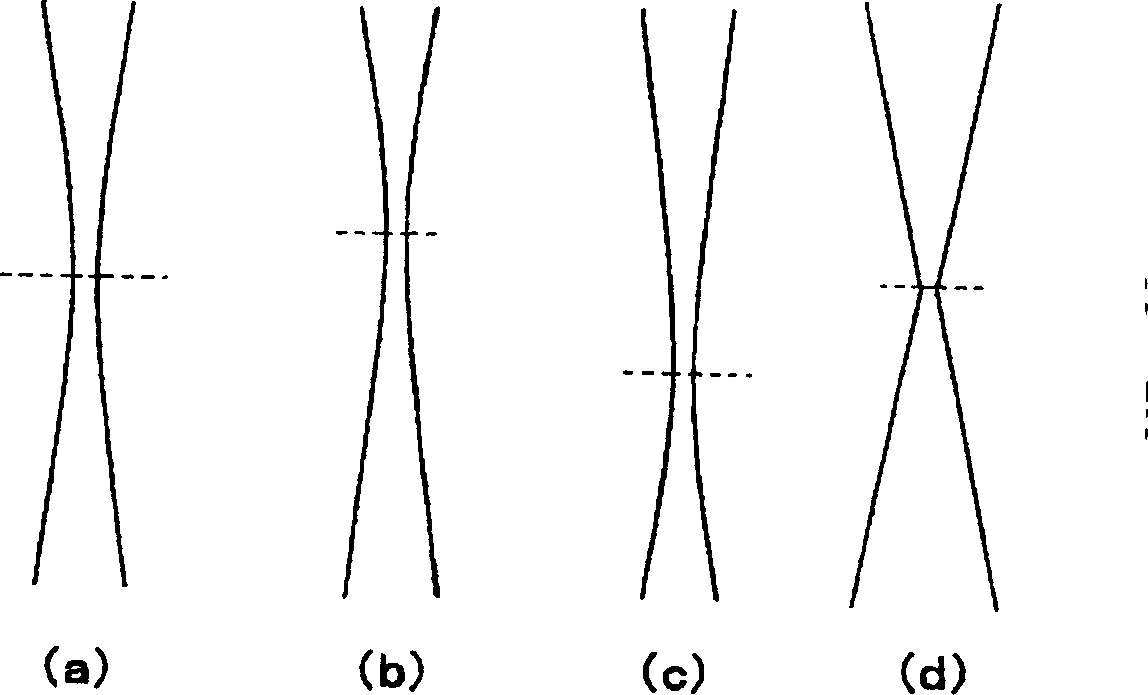
[0026] One of the features of the present invention is the style of the inner cavity shape of the needle tubular plastic top part and the drip core part, for example image 3 Shown (a) ~ (d) form.
[0027] image 3 Among them, the middle part is indicated by a dotted line, the middle part of the lumen shown in (a) forms the R part, the inner cavity shown in (b) forms the R part upward from the middle part, and the inner cavity shown in (c) goes down from the middle part The R portion is formed, and the R portion is not formed in the middle portion of the lumen shown in (d).
[0028] Have again, the high smoothness of the wall of the inner cavity is better to achieve the purpose of the present invention, the smoothing of the wall of the inner cavity is when the drip core part A and the needle tubular plastic top part B are made, the wall of the inner cavity Grinding with abrasives, for example, grinding with 1000# abrasive cloth.
Embodiment
[0030] The present invention is specifically described below in conjunction with the examples.
[0031] Example 1
[0032] according to figure 2 As shown, the infusion wick of this embodiment is composed of an infusion wick part A and a needle-shaped plastic tip part B, and is formed of polyolefin resin. The length of the dripping part of the needle tubular plastic tip part B is 5.0mm, the inner diameter of the opening is 0.5mm, and the outer diameter of the opening is 0.9mm.
[0033] Further, the total length of the rib C formed at the drip core portion and the needle tubular plastic tip portion B was 11.5 mm. In this embodiment, four ribs C are provided, and the shape of the ribs is tapered from top to bottom.
[0034] In the inner cavity 27, the middle part E with the smallest inner diameter is formed at a position 5.24 mm away from the opening part B of the needle-shaped plastic top part. The inner diameter of the middle part E is 0.48 mm, and the diameter of the middl...
PUM
 Abstract
Description
Claims
Application Information
 - R&D
- Intellectual Property
- Life Sciences
- Materials
- Tech Scout
- Unparalleled Data Quality
- Higher Quality Content
- 60% Fewer Hallucinations
Browse by: Latest US Patents, China's latest patents, Technical Efficacy Thesaurus, Application Domain, Technology Topic, Popular Technical Reports.
© 2025 PatSnap. All rights reserved.Legal|Privacy policy|Modern Slavery Act Transparency Statement|Sitemap|About US| Contact US: help@patsnap.com


