Paper clamping board

A technology of cardboard and lining board, applied in file folders, printing, etc., can solve the problems that it is difficult to know whether pressing the brake part 4 can close the clamping board, it is difficult to close the clamping body 3, and it is difficult to open the clamping body, etc.

Inactive Publication Date: 2006-11-08
LIHIT LAB INC
View PDF0 Cites 2 Cited by
  • Summary
  • Abstract
  • Description
  • Claims
  • Application Information

AI Technical Summary

Problems solved by technology

to this end, Figure 19 In the shown clamping board 1, it is difficult to know whether pressing the brake part 4 can close the side 3a of the clamping body 3 of the clamping board 1, and it is difficult to close the clamping body 3
[0008] in addition, Figure 20 In the sticky note clamping plate 5 shown, when one side 7a of the clamping body 7 faces the bottom plate 6 and opens, the operating part 8 must be pulled upwards
to this end, Figure 20 In the sticky note splint 5 shown, when the clamping body 7 is opened, it is difficult to operate the operating part 8, and it is difficult to open the clamping body 7

Method used


Image

  • Paper clamping board
  • Paper clamping board
  • Paper clamping board

Examples


Embodiment Construction

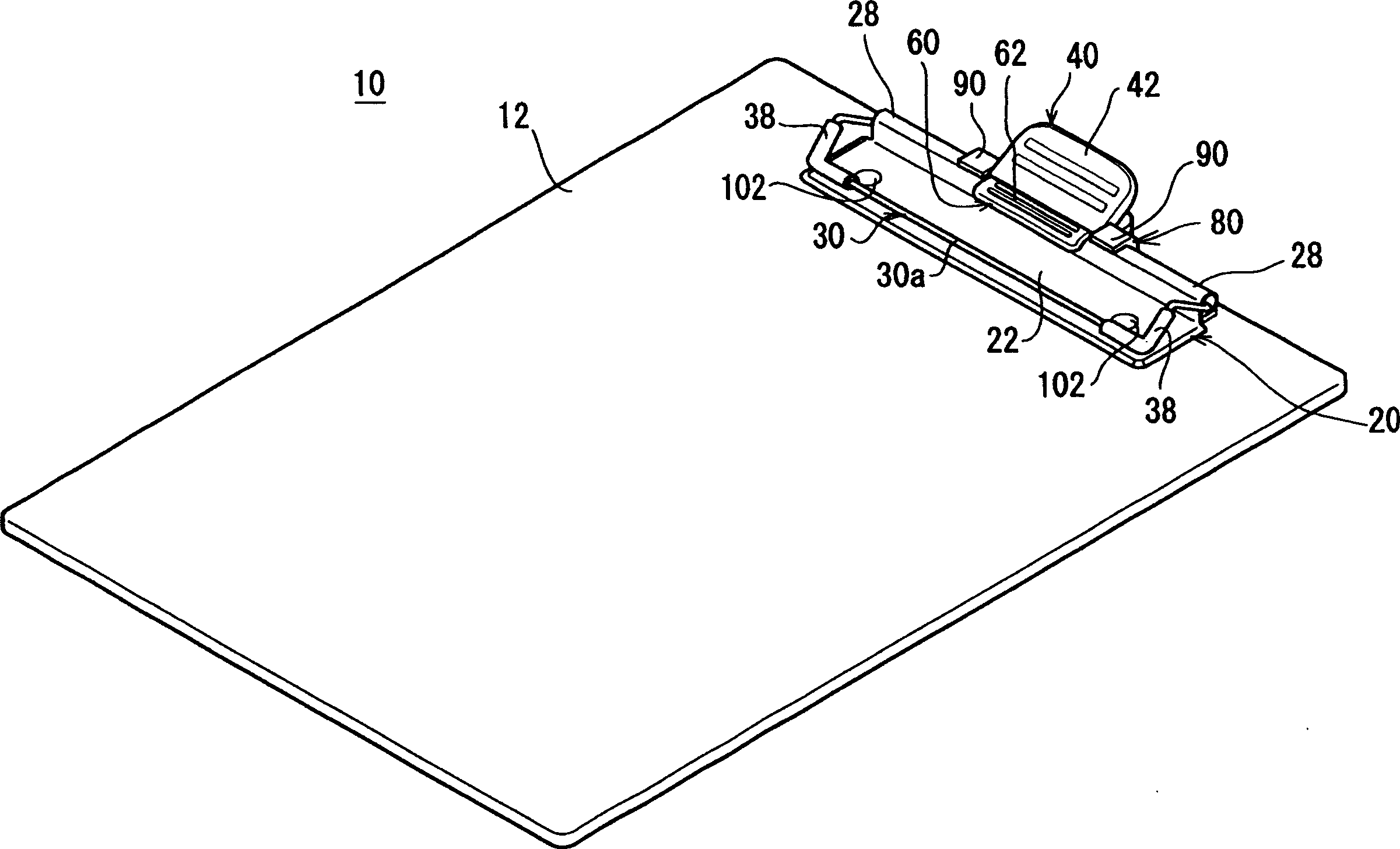
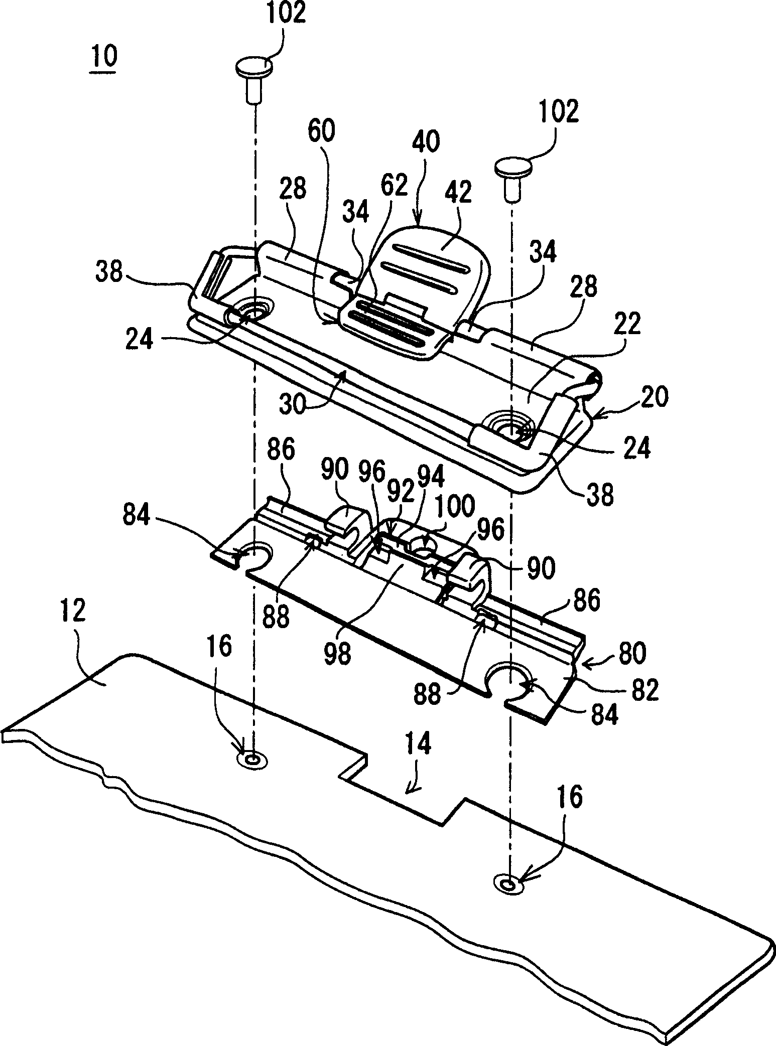
[0038] figure 1 It is a perspective view of an example of the clipboard of the present invention, figure 2 yes figure 1 An exploded perspective view of the main parts of the clipboard shown. figure 1 The illustrated paperboard 10 includes, for example, a rectangular base plate 12 molded of synthetic resin. One end of the bottom plate 12 is formed with a rectangular notch 14 as shown. Two circular mounting holes 16 , 16 are formed at regular intervals on both sides of the notch 14 on the bottom plate 12 .

[0039] On the bottom plate 12 are fixed a metal base 20 formed of a metal such as stainless steel and a resin base 80 formed of a synthetic resin such as ABS resin as a backing plate.

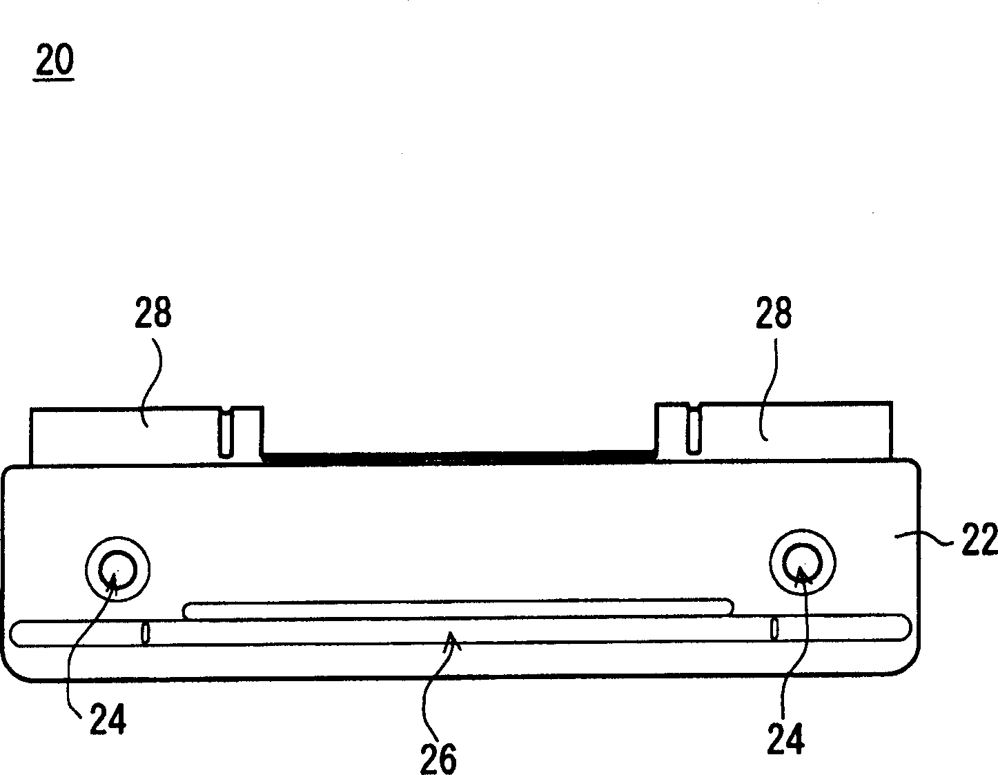
[0040] Such as image 3 and 4 As shown, the metal base 20 includes a rectangular plate-shaped main surface member 22 . Two circular mounting holes 24, 24 are formed at regular intervals on the main surface member 22. As shown in FIG. In addition, one end of the main surface member...


PUM


Abstract

The utility model relates to a cardboard, which can keep the clamping body in an open state and the clamping body is easy to open and close. The metal base (20) and the resin base (80) are fixed on the bottom plate (12) of the cardboard (10) as lining boards. The middle part (30b) of the holding body (30) is supported on the metal base (20) and can rotate. One side (30a) of the holder (30) is pressed against the main surface member (22) side of the metal base (20) by a coil spring (32). The other side (30c) of the holding body (30) forms an opening operation member (40) for opening the holding body (30). The resin base (80) is formed with an engaging member (94) that engages with the opening operation member (40) when the holder (30) is opened. One side (30a) of the opening operating member (40) forms the closing operating member (60) where the coupling member (94) disengages from the opening operating member (40) to close the clamping body (30).

Description

technical field [0001] The invention relates to a cardboard, in particular to a cardboard with a clamping body arranged on a bottom plate, for example, capable of clamping files and the like. Background technique [0002] An example of a conventional paperboard based on the present invention is disclosed in Patent No. 2623232. Figure 19 It is a perspective view of a conventional clipboard. Such as Figure 19 The shown clipboard 1 comprises a base plate 2 . A clamping body 3 is provided at the end of the bottom plate 2 . One side 3a of the clamping body 3 leans against the bottom plate 2 through a torsion spring (not shown). For this purpose, documents and the like can be clamped by means of the bottom plate 2 and one side 3 a of the clamping body 3 . A stop member 4 is provided near the other side 3 b of the clamping body 3 . The stopper member 4 fixes the holding body 3 in a state where one side 3 a of the holding body 3 is opened against the abutting force of the tors...

Claims


Application Information

Patent Timeline
Patent Type & Authority Patents(China)
IPC IPC(8): B42F9/00
Inventor 田中莞二新井裕中野浩
Owner LIHIT LAB INC
Why Eureka
Try Eureka