Supercharge Your Innovation With Domain-Expert AI Agents!

Reference point talbot encoder

An encoder and optical encoder technology, which is applied in the field of optical encoders and can solve problems such as the impact of accuracy

Inactive Publication Date: 2007-01-03
GSI卢姆莫尼克公司
View PDF13 Cites 0 Cited by
  • Summary
  • Abstract
  • Description
  • Claims
  • Application Information

AI Technical Summary

Problems solved by technology

[0006] A problem with such known downsized encoders is that the downsizing often negatively affects their accuracy

Method used


Image

  • Reference point talbot encoder
  • Reference point talbot encoder
  • Reference point talbot encoder

Examples


Embodiment Construction

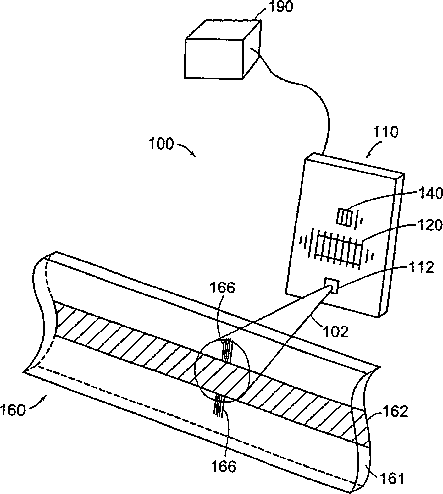
[0026] figure 1 A perspective view of a diffractive optical encoder 100 constructed in accordance with the present invention is shown. As shown, the encoder 100 includes three basic elements: an optoelectronic assembly or probe 110 ; a scale 160 and a signal processor 190 .

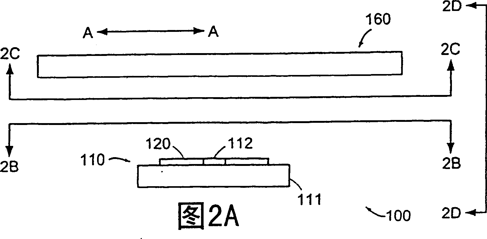
[0027] FIG. 2A shows a side view of encoder 100 . Figure 2B A view of probe 110 taken along line 2B-2B shown in FIG. 2A is shown. FIG. 2C shows a view of scale 160 taken along line 2C-2C shown in FIG. 2A. FIG. 2D shows an end view of encoder 100 taken along line 2D-2D shown in FIG. 2A. For ease of illustration, the signal processor 190 is not shown in FIGS. 2A-2D.

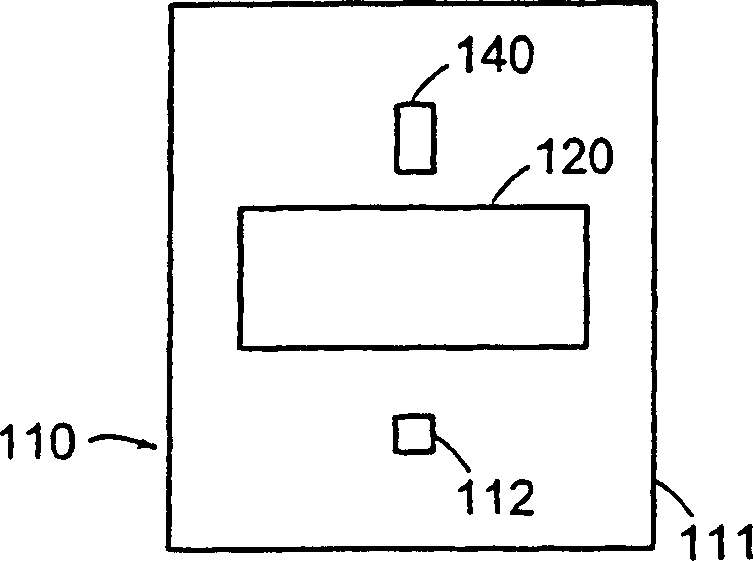
[0028] refer to figure 1 and 2A-2D, probe head 110 includes light source 112 , main detector array 120 , and marker or reference point detector 140 . As shown, the light source 112 and the detectors 120 , 140 are mounted on the same substrate 111 . Main detector array 120 and marker detector 140 are preferably implemented on a silicon ...


PUM


Abstract

The disclosed optical encoder includes a scale and a sensor head. The scale includes an optical element. The sensor head includes a light source, a detector array, and an index detector all of which are disposed on a substrate. The scale is disposed opposite the sensor head and is disposed for movement relative to the sensor head. The distance between the scale and the sensor head is selected so that the detector array lies near a talbot imaging plane. The light source emits a diverging beam of light, which is directed towards the scale. Light from the diverging beam of light is diffracted by the grating towards the detector array. Light from the diverging beam of light is diffracted by the optical element towards the index detector. The detector array provides a measurement of the position of the sensor head relative to the scale. The index detector provides a reference measurement of the position of the sensor head relative to the scale.

Description

[0001] Related application reference [0002] This application is related to [Attorney Docket No.MCE-018(111390-140)] entitled "HARMONIC SUPPRESSINGPHOTODETECTOR ARRAY" assigned to the assignee of this application and filed concurrently with this application Pending US Patent Application Serial No. 60 / 316,121. This application is hereby incorporated by reference in its entirety. Background technique [0003] The present application relates to an optical encoder. In particular, the present invention relates to an improved reference point optical encoder. [0004] Diffractive optical encoders are well known in the field of displacement detection systems. Such devices are commercially available from the assignee of the present invention, as well as from various other manufacturers. Examples of known optical encoders are described in US Patent Nos. 5,559,600 and 5,646,730. [0005] A recent development trend is to develop downsized diffraction-based encoders. Examples of suc...

Claims


Application Information

Patent Timeline
Patent Type & Authority Patents(China)
IPC IPC(8): G01D5/38G01D5/245G02B27/44G01D5/36
CPCG01D5/38G01D5/366G01D5/2457
Inventor 威廉·G·索伯恩诺曼·J·托比梅尔文·J·J·特尔道格拉斯·A·克林拜尔拉尔夫·A·凯利埃尔
Owner GSI卢姆莫尼克公司
Features
  • R&D
  • Intellectual Property
  • Life Sciences
  • Materials
  • Tech Scout
  • Unparalleled Data Quality
  • Higher Quality Content
  • 60% Fewer Hallucinations
Learn More