Wring-out device for cleaning element for wetting and moisting cleaning tool

A technology of cleaning components and wet method, which is applied in the direction of cleaning equipment, cleaning machinery, carpet cleaning, etc., and can solve the problems of increasing the difficulty of operating the wringer device

Inactive Publication Date: 2007-02-07
CARL FREUDENBERG KG
View PDF7 Cites 2 Cited by
  • Summary
  • Abstract
  • Description
  • Claims
  • Application Information

AI Technical Summary

Problems solved by technology

This increases the difficulty of operating the wringer

Method used


Image

  • Wring-out device for cleaning element for wetting and moisting cleaning tool
  • Wring-out device for cleaning element for wetting and moisting cleaning tool
  • Wring-out device for cleaning element for wetting and moisting cleaning tool

Examples


Embodiment Construction

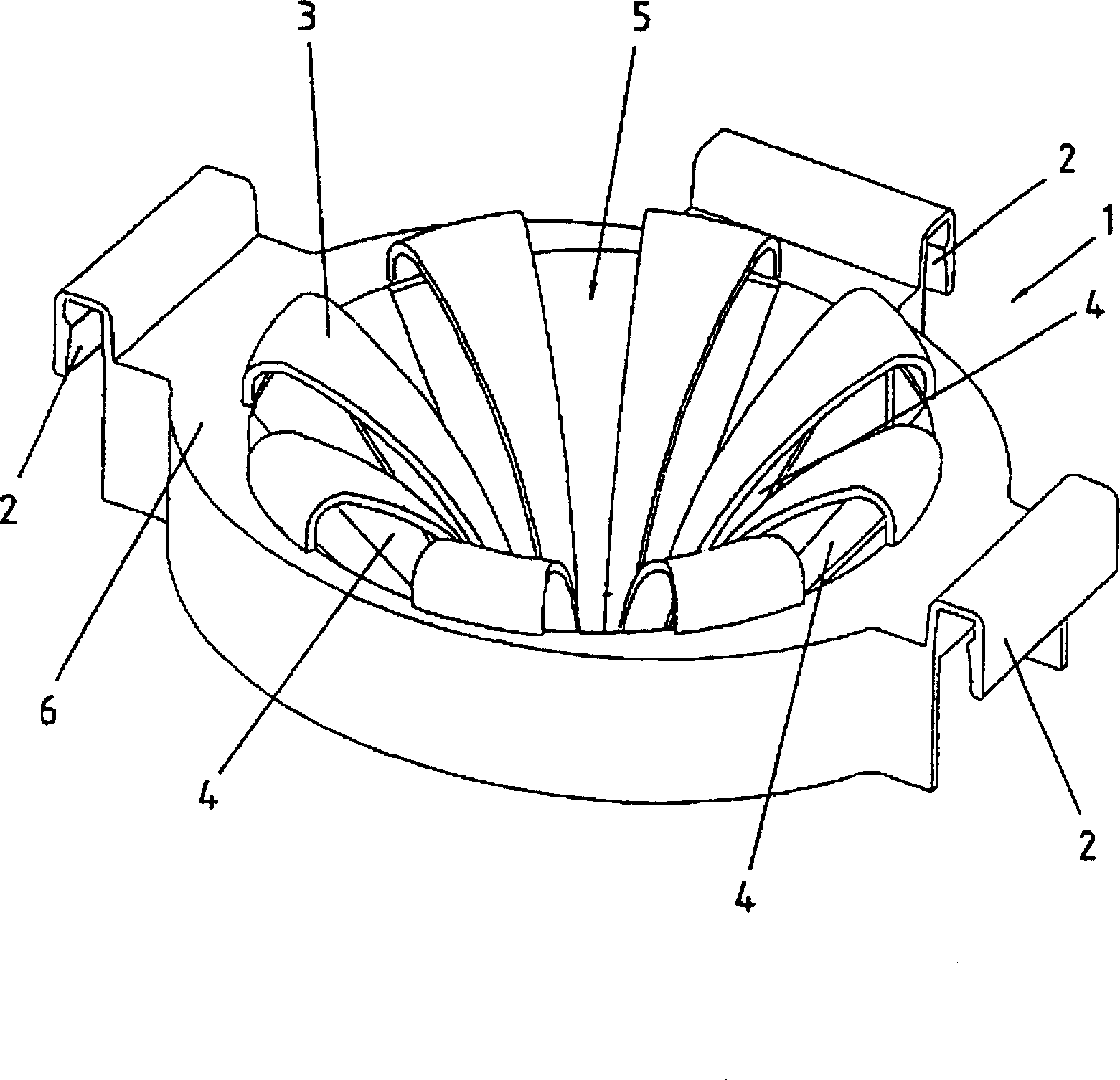
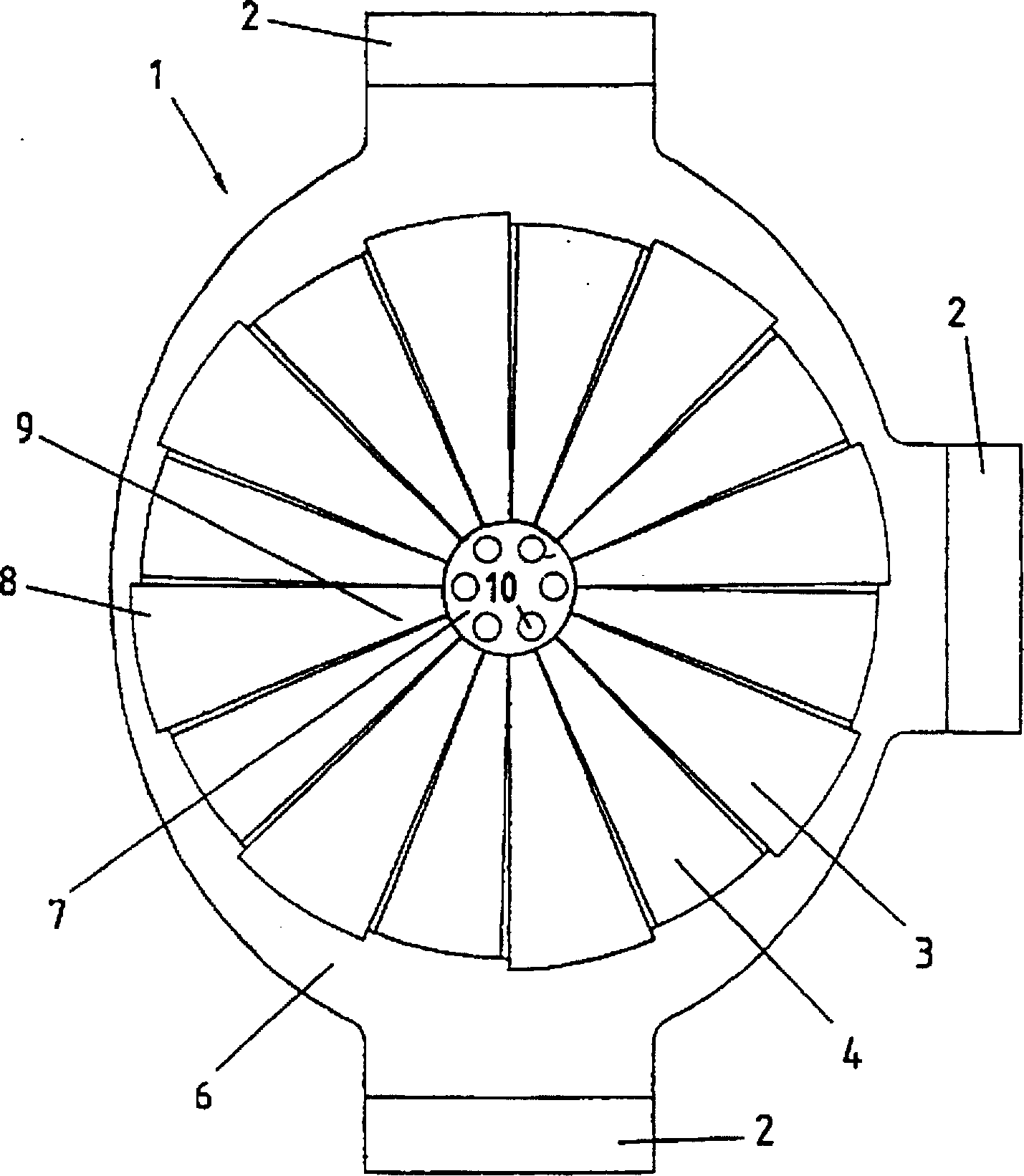
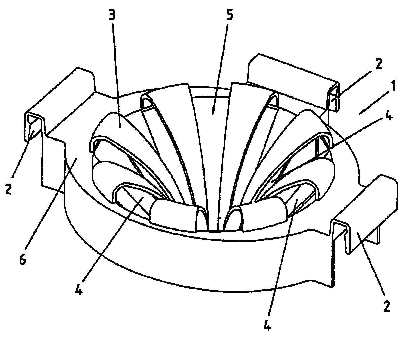
[0019] figure 1 A perspective view of an embodiment of the wringing device of the present invention is shown in FIG. The wringer device is formed by means of a receptacle 1 , the access opening above which a cleaning element such as a scrubbing mop can be inserted and wrung out in a squeeze cage 5 .

[0020] The wringing is effected by a downwardly directed pressing force of the mop and possibly also by turning and twisting of the mop.

[0021] The extrusion cage 5 is formed by elastically formable wall parts 3 which are formed in the form of tongues and which taper downwards from a support frame 6 of the receptacle 1 to form a cage. Each spring element 3 has a convex curvature and forms in the cage an inner diameter which increases when the cleaning element is pressed in, in other words the curvature of the spring element decreases. Each spring element 3 has an upper end 8 which is preferably arch-shaped and is formed on the carrier frame 6 . If one imagines a tangent at t...


PUM


Abstract

A wringing device for cleaning elements of wet and moist mops, the wringing device having a liquid-permeable receptacle (1) which can be affixed to a container, and in which a cleaning element can be wrung out by the exertion of pressure, the receptacle having deformable wall parts (3) and the inside width of the receptacle changing when the cleaning element is pressed in due to the effective force of pressure, wall parts being formed from spring elements (3) with convex curvature, which can be deformed by exertion of pressure for the purpose of enlarging the inside width.

Description

technical field [0001] The invention relates to a wringing device for cleaning elements of wet and wet scrubbing implements, which has a liquid-permeable receptacle which can be fastened to a water reservoir, into which the cleaning element can be wrung out, wherein The receptacle has a plurality of formable wall parts and the inner diameter of the receptacle can be changed by the effective press-in force when the cleaning element is pressed in. The invention also relates to wet and wet cleaning devices. Background technique [0002] Such a wringer is known from EP 0489237. The wringer has a liquid-through container which is fastened to the edge of the scrubbing bucket and a wet mop can be wrung out by pressing into the container. The receptacle is funnel-shaped and includes a plurality of elastically deformable wall parts spaced apart from one another. These wall parts are arched and fastened with their outer legs to the support frame of the receptacle, while their inner...

Claims


Application Information

Patent Timeline
Patent Type & Authority Patents(China)
IPC IPC(8): A47L13/58
CPCA47L13/58
Inventor 乌韦·丁格特
Owner CARL FREUDENBERG KG
Why Eureka
Try Eureka