Mop wringer

a wringer and mops technology, applied in the field of wringers, can solve the problems of requiring unnatural posture, placing unnecessary stress and strain on hands, wrists, backs, etc., and achieves the effects of reducing force and posture factors, facilitating wringing wet mops, and improving productivity

Inactive Publication Date: 2004-01-06
GROMWELL
View PDF3 Cites 32 Cited by
  • Summary
  • Abstract
  • Description
  • Claims
  • Application Information

AI Technical Summary

Benefits of technology

It is another object of the invention to provide a mop wringer designed to make it easier to wring wet mops, thus improving productivity and reducing force and posture factors as work-related musculoskeletal disorders.
It is yet another object of the invention to provide a mop wringer utilizing components made of or plastic material, such as high-density polyethylene, that will be mostly rigid but slightly flexible and readily fabricated as by suitable injection molding, and easily fabricated metal hardware used as connectors and cross members.
The mop wringer of my invention easily and effortlessly wrings excess liquid out of a mop. A foot pedal cooperative with connecting arms and disk links actuates a movable squeeze plate to wring excess liquid out of a wet mop. The operator need only step with one foot and moderate body weight on the foot pedal. Erect posture is maintained during the wringing process. The operator does not have to push, pull, or twist the mop handle during the wringing process.

Problems solved by technology

Wet mop wringers in use or shown in the art use downward pressure and sideways pressure by the custodian, which require an unnatural posture when pressing on the pressure handle during wringing.
The wringing motion, posture, and force required by downward and sideways wet mop wringers might place unnecessary stresses and strains on the hand, wrist, shoulder, back, and legs.

Method used


Image

  • Mop wringer
  • Mop wringer
  • Mop wringer

Examples


Embodiment Construction

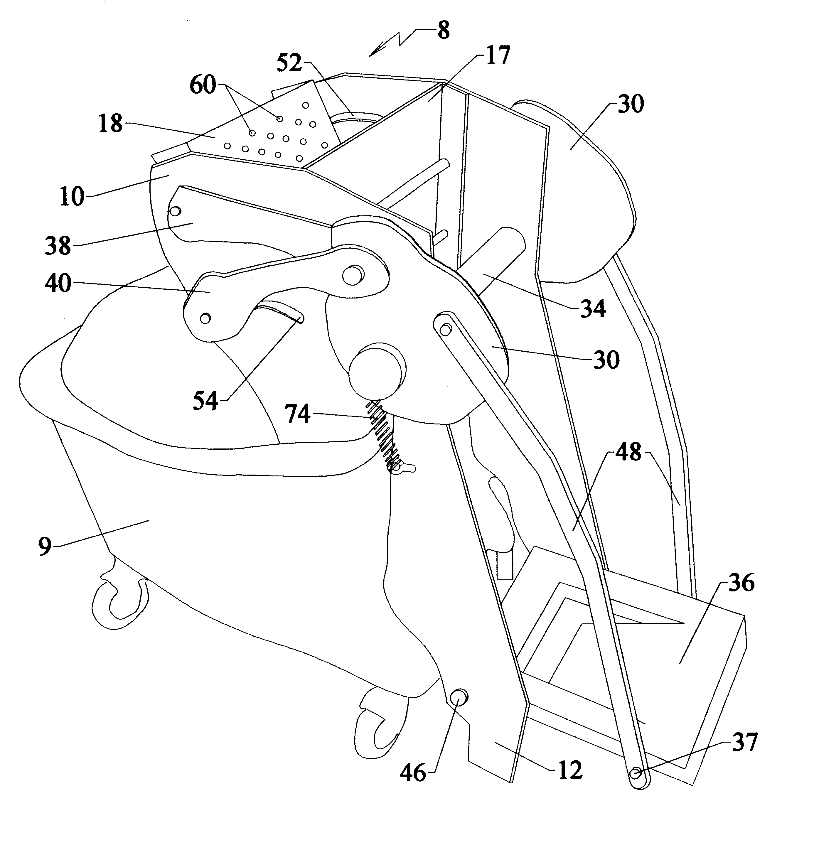
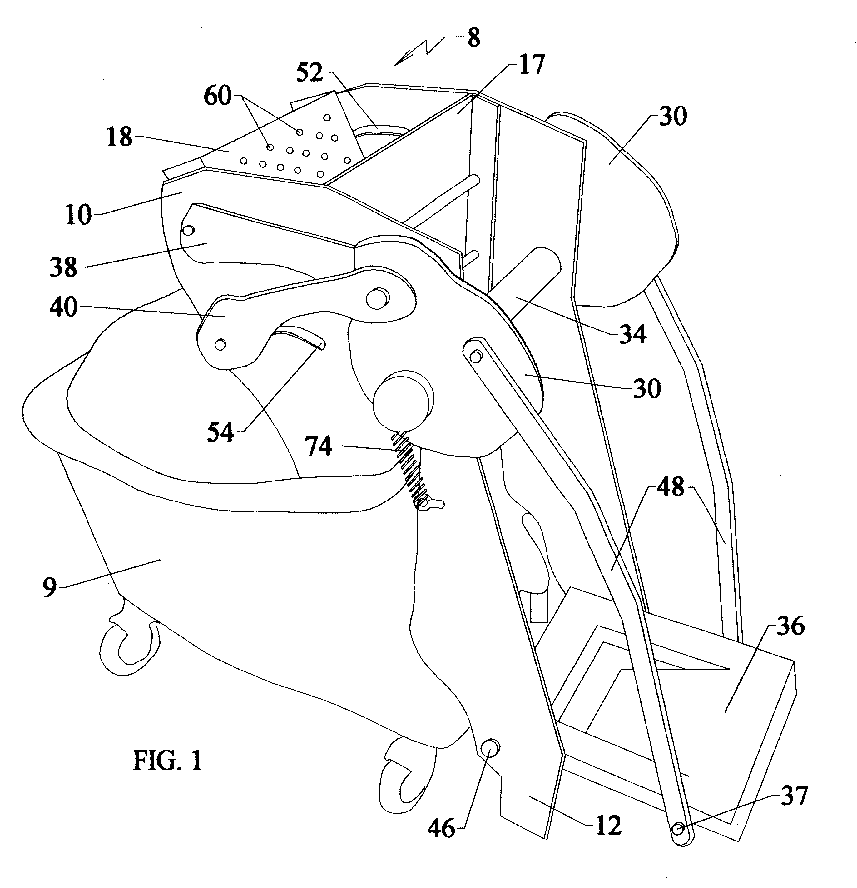
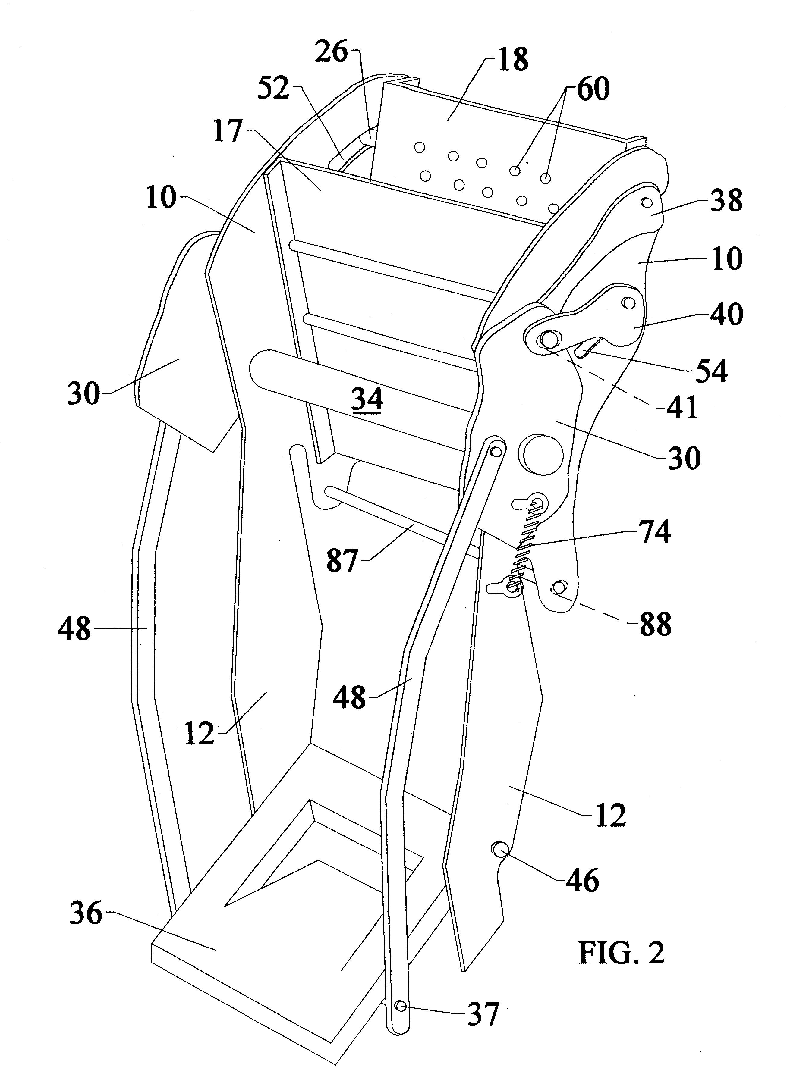
The mop wringer, indicated generally by the numeral 8, is positioned on the rim of a mop bucket 9 or other suitable receptacle, as shown in FIG. 1. The wringer includes a pair of spaced frame members or lateral plates 10, each having a downwardly depending extension or leg 12, thereby defining a groove 13 to allow the wringer to rest on the rim of the bucket 9. The bottom marginal edge of each extension 12 terminates above the floor, thereby providing stability by pressing against the floor as the foot pedal is depressed during the wringing step.

The lateral plates 10 are provide with aligned openings 45 that accommodate and hold the lower-most axle 46 which spans the leg extensions 12 of the spaced lateral plates 10. Similarly, the upper axle 34 is passed through and held by aligned openings 33, and axle 34 spans the spaced lateral plates 10. Disk links 30 are mounted on the opposed ends of the upper axle 34 and to the outside of the lateral plates. It is understood by one skilled i...


PUM


Abstract

A mop wringer having a pair of spaced frame members or lateral plates, each having a lower leg member, and includes structure for attaching the wringer to a receptacle. A stationary squeeze plate and a movable squeeze plate are located in the space between the frame members and between which the mop may be placed for wringing, the movable squeeze plate pivoting about a middle axle extending between the frame members. A foot pedal is pivotally connected to the lower leg members about a lower-most axle. An upper axle, disposed above the middle axle, extends through and between the frame members. One or more disks are mounted about the upper axle adjacent each of the frame members, the disk being connected to an upper portion of the movable squeeze plate by one or more connecting arms. Second connecting arms interconnect the foot pedal to the outside disks. A coiled steel spring, is operatively connected between the disks and the adjacent frame member and one of the connecting arms between the outside disk and the movable squeeze plate. When the user depresses the foot pedal, the movable squeeze plate is pivoted toward the stationary squeeze plate, and when released, the movable squeeze plate is returned to a rest position.

Description

This invention relates to custodial equipment utilized for wringing a wet mop. In its more specific aspect, this invention relates to a mop wringer such as used by a building custodian for wringing excess liquid from a mop.BACKGROUND OF THE INVENTION AND PRIOR ARTWet mop wringers in use or shown in the art use downward pressure and sideways pressure by the custodian, which require an unnatural posture when pressing on the pressure handle during wringing. These mop wringers also require that significant force be exerted on the palm of the hand when pressing on the pressure handle during wringing. The wringing motion, posture, and force required by downward and sideways wet mop wringers might place unnecessary stresses and strains on the hand, wrist, shoulder, back, and legs.OBJECTS OF THE INVENTIONThis invention has therefore as an object is to provide an ergonomical alternative to sideways pressure and downward pressure required for conventional mop wringers.It is another object of ...

Claims


Application Information

Patent Timeline
Patent Type & Authority Patents(United States)
IPC IPC(8): A47L13/10A47L13/59
CPCA47L13/59
Inventor GROMNICKI, MARTIN F
Owner GROMWELL
Why Eureka
Try Eureka