
Centrol hole shape asymmetrical high-density CD recording medium and making method thereof

A recording medium, a medium technology, applied in the recording/reproducing by optical methods, manufacturing of optical record carriers, optical record carriers, etc., can solve problems such as irreparable damage of objective lens OL and/or servo mechanism

Inactive Publication Date: 2007-03-14
LG ELECTRONICS INC
View PDF2 Cites 0 Cited by
  • Summary
  • Abstract
  • Description
  • Claims
  • Application Information

AI Technical Summary

Problems solved by technology

As a result, HD-DVD10, objective lens OL and / or servo mechanism may be irreparably damaged

Method used


Image

  • Centrol hole shape asymmetrical high-density CD recording medium and making method thereof
  • Centrol hole shape asymmetrical high-density CD recording medium and making method thereof
  • Centrol hole shape asymmetrical high-density CD recording medium and making method thereof

Examples


Embodiment Construction

[0034] Embodiments employing the principles, features, and concepts of the present invention are described below with reference to the drawings.

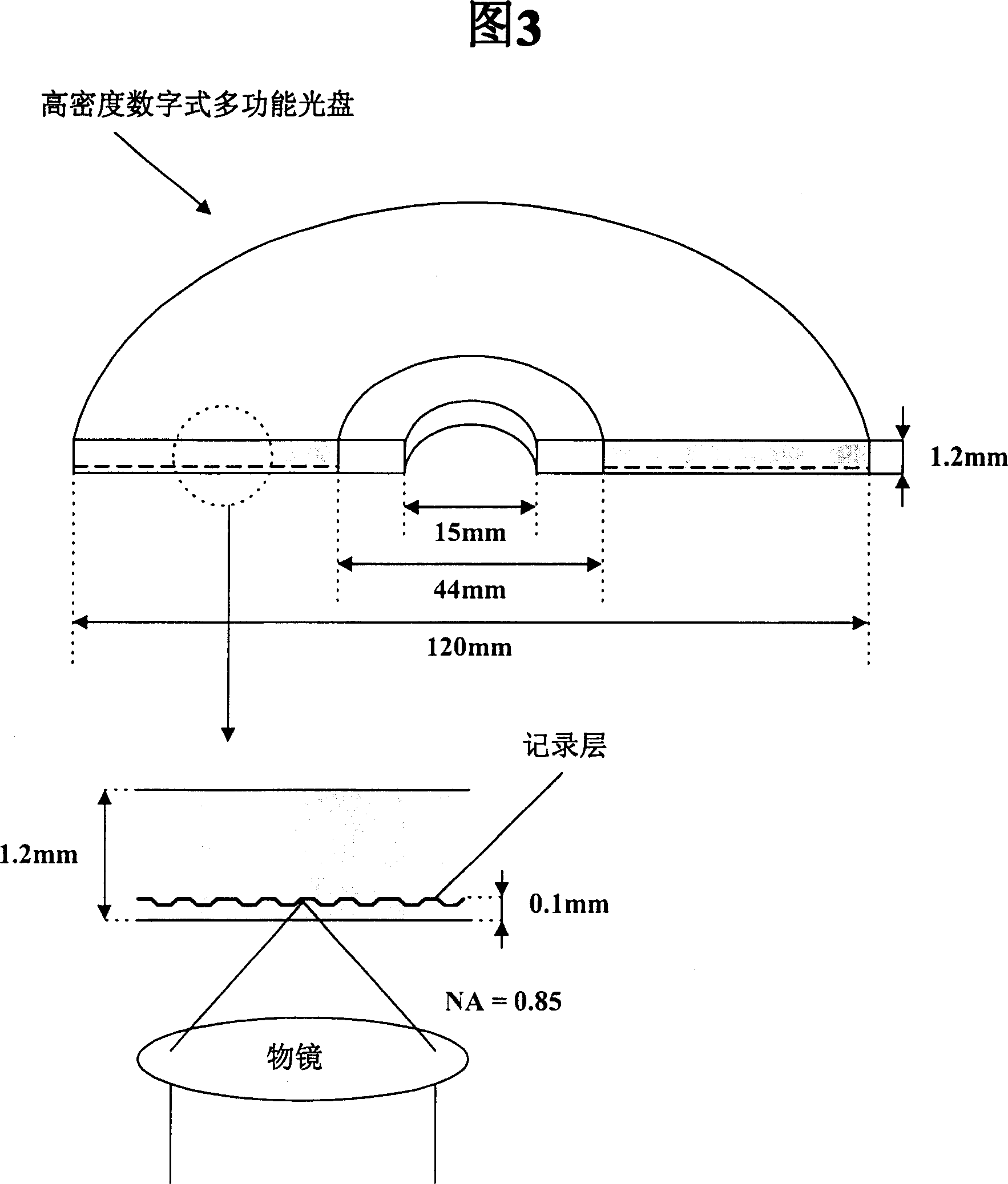
[0035] Fig. 6 is a partial view showing the structure of the first embodiment of the high-density optical disc according to the present invention. Embodiments of the high-density optical disc in the present invention, such as HD-DVD, have the same dimensions as the traditional HD-DVD shown in Figure 3, namely thickness 1.2mm diameter 120mm, central hole maximum diameter 15mm and surrounding central hole The diameter of the clamping area is 44mm. Moreover, when the HD-DVD appearing in FIG. 6 is normally placed in the optical disc device, its recording layer containing the concave pattern will be at least about 0.1 mm away from the objective lens of the optical sensor as described above.

[0036] However, the HD-DVD of the present invention in FIG. 6 has a clamping region structure such that its central hole is asymmetrical about an ...


PUM

PropertyMeasurementUnit
diameteraaaaaaaaaa
diameteraaaaaaaaaa
angleaaaaaaaaaa

Abstract

The present invention relates to a high-density disk that is structured to prevent a collision of an optical pickup's objective lens with the high-density disk if the disk is placed upside down in a disk device that is able to record and reproduce signals to / from the high-density disk. A high-density disk recording medium according to the present invention is structured such that, wherein a recording layer having high-density pit patterns is offset from a center plane of disk thickness, a center hole of the disk recording medium is asymmetric in shape with respect to the center plane where, for example, both entrances of the center hole have mutually different diameters.

Description

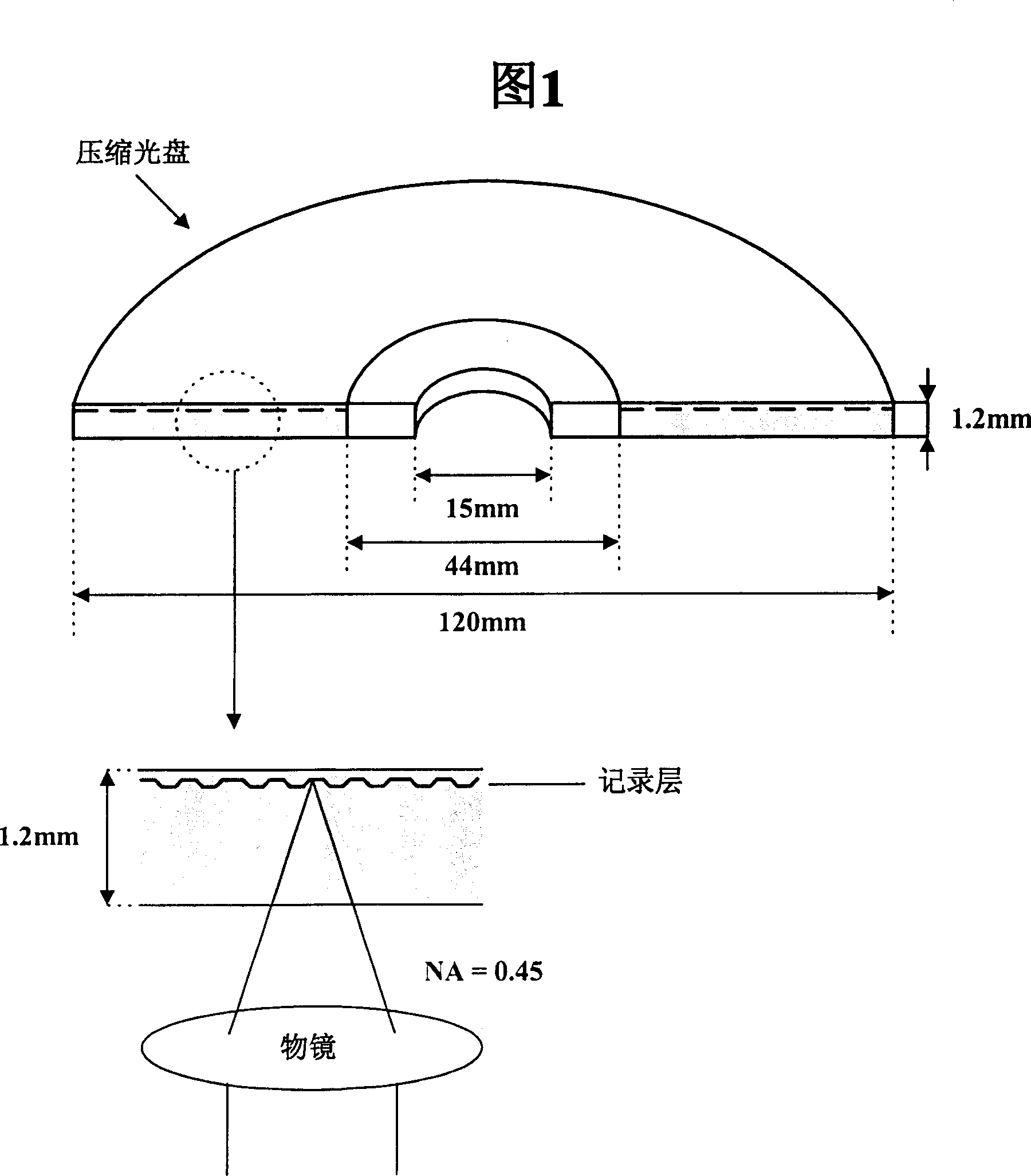
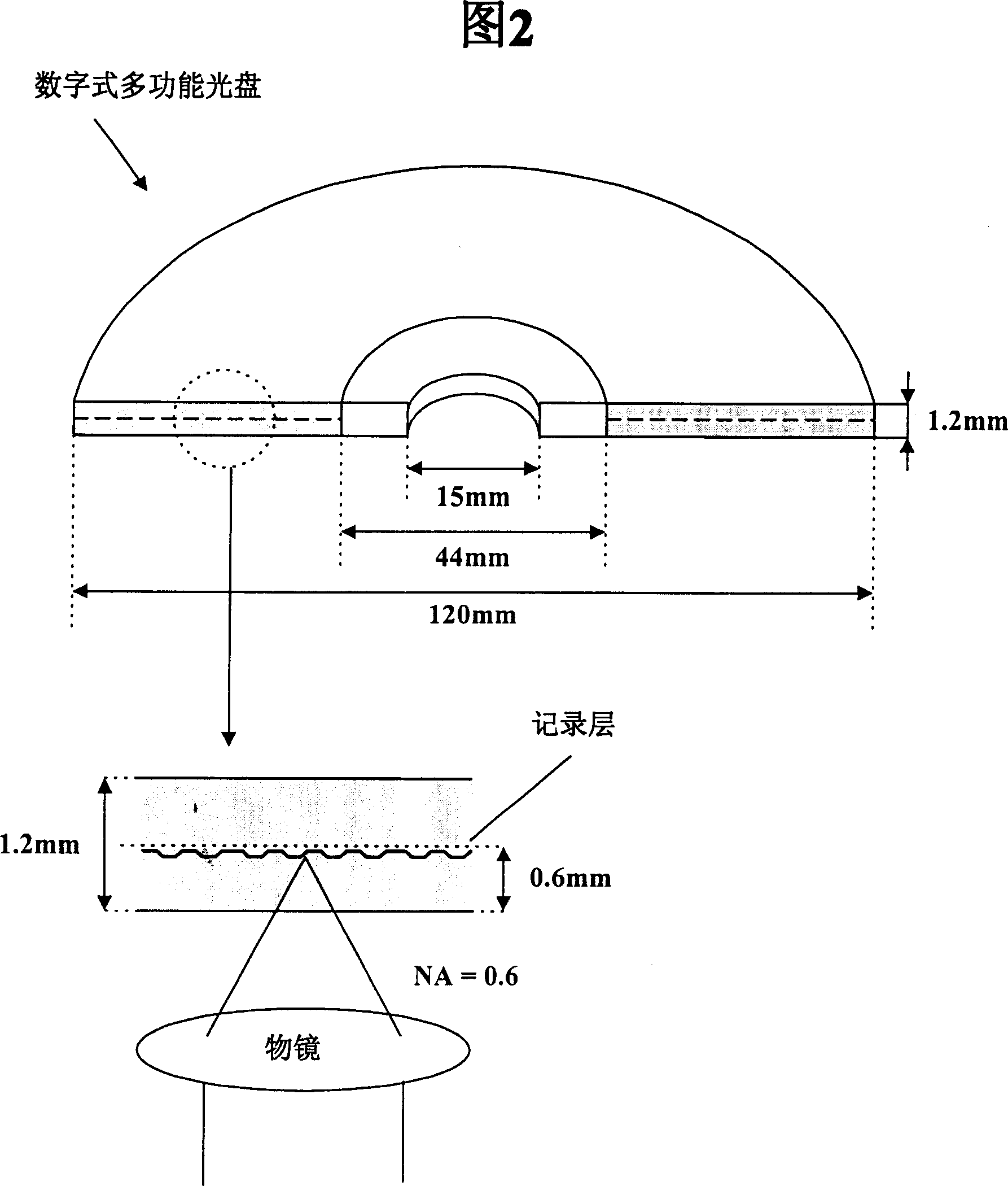
technical field [0001] The present invention generally relates to a high-density optical disc structure and a manufacturing method thereof, more specifically, to a high-density optical disc structure capable of preventing an objective lens of an optical sensor from colliding with a high-density optical disc. Background technique [0002] The compact disc (CD) shown in Figure 1 has a thickness of 1.2 mm and a diameter of 120 mm. The CD has a central hole with a diameter of 15mm and a clamping area around the central hole of 44mm. The clamping area is an area clamped by a clamp on a spindle or a turntable mounted on an optical disc device. [0003] When a CD is normally placed on an optical disc device, its recording layer having a concave pattern is only about 1.2 mm away from the objective lens of the photosensor. The CD objective has a numerical aperture (NA) of 0.45, which is relatively small. [0004] As shown in FIG. 2, a digital versatile disc (DVD) is similar to a C...

Claims


Application Information

Patent Timeline
Patent Type & Authority Patents(China)
IPC IPC(8): G11B7/00G11B7/24G11B7/26G11B17/028G11B23/00
CPCG11B23/0035G11B7/24
Inventor 金进镛朴景灿
Owner LG ELECTRONICS INC
Learn More