Butterfly valve

A butterfly valve and valve body technology, applied in the field of butterfly valves, can solve the problems of seat ring deterioration, failure to achieve sealing, failure to promote sealing, etc.

Inactive Publication Date: 2007-04-11
OKUMURA ENG
View PDF21 Cites 0 Cited by
  • Summary
  • Abstract
  • Description
  • Claims
  • Application Information

AI Technical Summary

Problems solved by technology

[0011] However, even if the ridge near the valve shaft is under pressure to a certain extent, sealing cannot be achieved until the peripheral portion of the valve body comes into contact with the ridge near the center. The crimping of the protruding strip near the valve shaft when the center is in contact still cannot promote sealing, so that the torque when the valve is closed becomes the main cause of the large useless torque
[0012] In addition, when the valve body rotates in the closing direction to reduce the flow rate, since the peripheral portion of the valve body is likely to come into contact with the protruding strip near the valve shaft, there is also the possibility of deterioration of the seat ring at this portion.

Method used


Image

  • Butterfly valve
  • Butterfly valve
  • Butterfly valve

Examples


Embodiment Construction

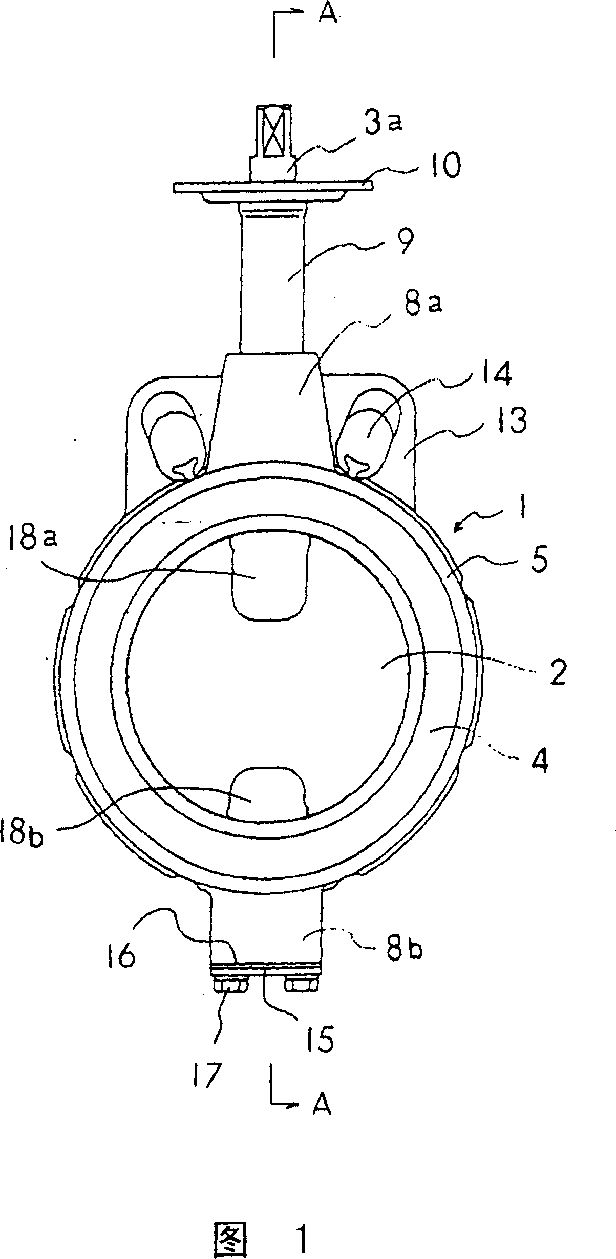
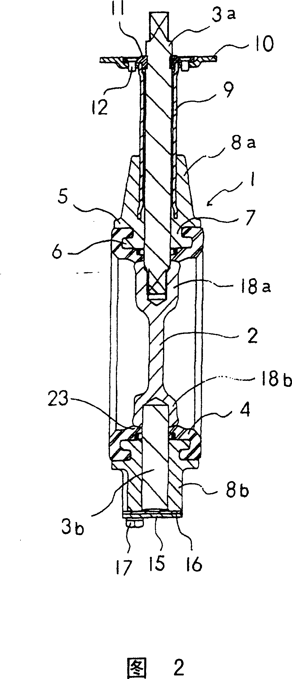
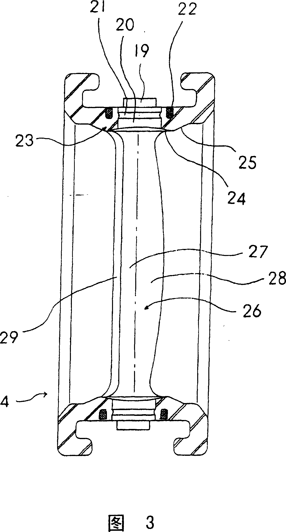
[0028] The embodiment of the butterfly valve of the present invention will be described below with the accompanying drawings. Fig. 1 is a front view of the butterfly valve of the present invention, Fig. 2 is a sectional view along the line A-A of Fig. 1, Fig. 3 is a sectional view of the seat ring along the direction of the valve axis, and Fig. 4 is a sectional view of the seat ring along the direction perpendicular to the valve axis.

[0029] The butterfly valve is set at the connecting part of the pipe that can flow in it, and performs on-off control and flow adjustment of the flow path. It has: an annular valve box 1, which is clamped by two pipes along its axial direction (flow path direction); A substantially disc-shaped valve body 2 installed inside the valve box 1; the valve body 2 is freely rotatably supported around the valve shaft 3 (the axis passing through the center of the valve box 1 in a direction perpendicular to the direction of the flow path). The valve rods ...


PUM


Abstract

The invention provides a butterfly valve, in which a valve element peripheral portion almost simultaneously abuts on protrusions of a seat ring. By gradually varying inclination of a pressure contact surface of the protrusion, the pressure contact surface in the vicinity of a valve shaft is sharply inclined, and the surface far from the valve shaft is gently inclined. The abutting portion of the pressure contact surface abutting on the peripheral portion of the valve element is expanded to an opening direction side more in a portion far from the valve shaft than in the vicinity of the valve shaft. The peripheral portion of the valve element almost simultaneously abuts on an abutting portions of protrusions of the peripheral portion of the valve element.

Description

technical field [0001] The invention relates to a butterfly valve which makes a valve body installed in a valve box rotate around a valve shaft so as to open, close and regulate the flow of the valve. Background technique [0002] The general butterfly valve is to make the roughly disc-shaped valve body installed in the valve box rotate around the valve shaft passing through the diameter direction of the valve body, to open, close or adjust the flow of the valve, and on the inner peripheral surface of the valve box Install the seat ring made of rubber-like elastomer. When the valve is closed, the seat ring is crimped by the peripheral part of the valve body because the valve body rotates around the valve shaft so that the plate surface is perpendicular to the direction of the flow path (closing direction), thereby forming a seal between the inner peripheral surface of the valve box and the valve body. [0003] Fig. 8 shows an example of the seat ring. The section of the op...

Claims


Application Information

Patent Timeline
Patent Type & Authority Patents(China)
IPC IPC(8): F16K1/22F16K1/226F16K3/06F16K25/00
CPCF16K1/226F16K1/46F16K27/0218
Inventor 福地正晴
Owner OKUMURA ENG
Why Eureka
Try Eureka