Multi-path connecting terminal for communication cable and its producing method and connecting method

A technology for communication cables and connectors, which is applied in the field of four-wire connectors for communication cables. It can solve the problems of damaged cable core wires, inconvenient observation of cable core wire connection quality, loose cable core wires, etc., and achieves low overall cost. , The operation process is clearly visible and the effect of speeding up

Inactive Publication Date: 2007-05-09
吴耀龄
View PDF3 Cites 2 Cited by
  • Summary
  • Abstract
  • Description
  • Claims
  • Application Information

AI Technical Summary

Problems solved by technology

The size of the knife edge designed by the current terminal is suitable for the diameter range of the cable core wire is φ0.4-0.9mm. Since a gap of one order of magnitude cannot meet the requirements of a large level difference, it will inevitably result in the connection of the cable core wire with a small diameter. Loose, large-diameter cable core wires result in damage to the core
The current terminal is composed of covers of various colors, which is inconvenient to observe the connection quality of the cable core wires

Method used


Image

  • Multi-path connecting terminal for communication cable and its producing method and connecting method
  • Multi-path connecting terminal for communication cable and its producing method and connecting method
  • Multi-path connecting terminal for communication cable and its producing method and connecting method

Examples


Embodiment 1

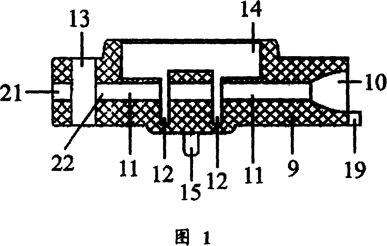
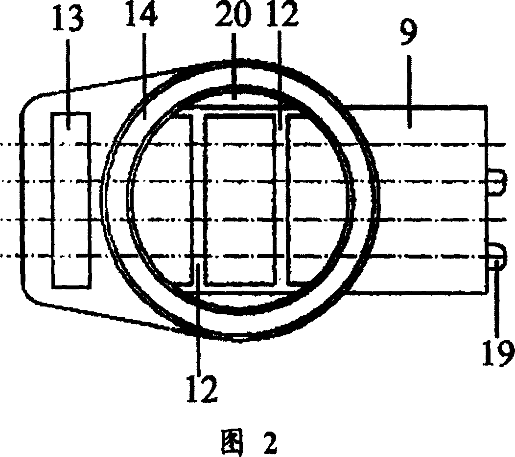
[0053] In the base (9), four wiring channels (11) are arranged relatively parallel to the base (9), and the wiring channels (11) penetrate from the front end of the base (9) to the rear end of the base (9), The port of the wiring channel (11) at the front end of the base (9) is provided with an extended mouth-shaped inlet guide (10), and the port of the wiring channel (11) at the rear end of the base (9) is provided with a test hole (21). The rear end of the base (9) is provided with a disconnection hole (13), and the disconnection hole (13) runs through the rear end of the base (9) relatively vertically with the wiring channel (11), and the wiring channel (11) and the disconnection hole ( 13) An outlet port (22) is provided at the intersection, and the wire inlet guide port (10), the wiring tunnel (11), the outlet port (22) and the test hole (21) are on the same axis. The front end of the base (9) is relatively parallel with several wire inlet marks (19), and the wire inlet m...

Embodiment 2

[0056] 6 wiring channels (11) are arranged relatively parallel to the base (9) in the base (9), and the wiring channels (11) penetrate from the front end of the base (9) to the rear end of the base (9), The port of the wiring channel (11) at the front end of the base (9) is provided with an extended mouth-shaped inlet guide (10), and the port of the wiring channel (11) at the rear end of the base (9) is provided with a test hole (21). The rear end of the base (9) is provided with a disconnection hole (13), and the disconnection hole (13) runs through the rear end of the base (9) relatively vertically with the wiring channel (11), and the wiring channel (11) and the disconnection hole ( 13) An outlet port (22) is provided at the intersection, and the wire inlet guide port (10), the wiring tunnel (11), the outlet port (22) and the test hole (21) are on the same axis. The front end of the base (9) is provided with a plurality of wire inlet marks (19) relatively parallel to each o...

Embodiment 3

[0059] In the base (9), four wiring channels (11) are arranged relatively parallel to the base (9), and the wiring channels (11) penetrate from the front end of the base (9) to the rear end of the base (9), The port of the wiring channel (11) at the front end of the base (9) is provided with an extended mouth-shaped inlet guide (10), and the port of the wiring channel (11) at the rear end of the base (9) is provided with a test hole (21). The rear end of the base (9) is provided with a disconnection hole (13), and the disconnection hole (13) runs through the rear end of the base (9) relatively vertically with the wiring channel (11), and the wiring channel (11) and the disconnection hole ( 13) An outlet port (22) is provided at the intersection, and the wire inlet guide port (10), the wiring tunnel (11), the outlet port (22) and the test hole (21) are on the same axis. The front end of the base (9) is relatively parallel with several wire inlet marks (19), and the wire inlet m...


PUM


Abstract

The invention method is to build wiring passage channel, wire incoming guid hole, testing hole, wire cutting hole, wire outletting hole, wire incoming hole sign and gland pool. The wire incoming guide hole, wiring passage channel, wire outletting hole and testing hole are at same axle centre, a press-cut lid is set in upper part of the gland pool, fixed plug and jointing clip and fit in the press-cut lid, pedestal is fixed in locating slot of wire position line frame, after finishing core wir threading operation in coming and going direction, to press the press-cut lid by a tool to make it completely into the gland pool, the insulatnig layer of core wire is broken by wire cutting clip set relatively parallel in pairs, metal wire in the core wire is squeezed into mouth of wire cutting clip and is connected with jointing clip.

Description

technical field [0001] The invention relates to a communication cable terminal connection device, in particular to a four-wire terminal for communication cables. Background technique [0002] In 1958, 3M Corporation of the United States invented the communication cable connector, and my country began to introduce it in the early 1980s. After nearly 20 years of use, no new form of connector has appeared. [0003] At present, the communication cable core wire connectors produced by domestic manufacturers are all produced in accordance with the requirements of the Ministry of Posts and Telecommunications, but only in the form of second-wire and third-wire connections. It is the same standard as the Ministry of Posts and Telecommunications of my country. [0004] The current wiring method of the terminal is to first twist the core wires to a length of 3-5cm. This kind of operation process will cause the twisted cable core wires to occupy the space of the connection length and ci...

Claims


Application Information

Patent Timeline
Patent Type & Authority Patents(China)
IPC IPC(8): H01R4/24H01R43/18H01R43/16
Inventor 吴耀龄
Owner 吴耀龄
Why Eureka
Try Eureka