Adapter connector

A technology of adapter card and connector, which is applied in the direction of connection and connection device parts, electrical components, etc., and can solve problems such as laborious replacement and extraction of adapter card a, damage to personnel or computer components, and failure to operate normally.

Inactive Publication Date: 2007-05-30
WONTEN TECH
View PDF3 Cites 0 Cited by
  • Summary
  • Abstract
  • Description
  • Claims
  • Application Information

AI Technical Summary

Problems solved by technology

However, no matter when the computer is in use or in the process of installation and transportation, it is inevitable to generate vibrations of different sizes. For the adapter card a and the socket b with a small error tolerance, the vibration often makes the adapter card a Not functioning properly due to being loose or misaligned
[0003]

Method used


Image

  • Adapter connector
  • Adapter connector
  • Adapter connector

Examples


Embodiment Construction

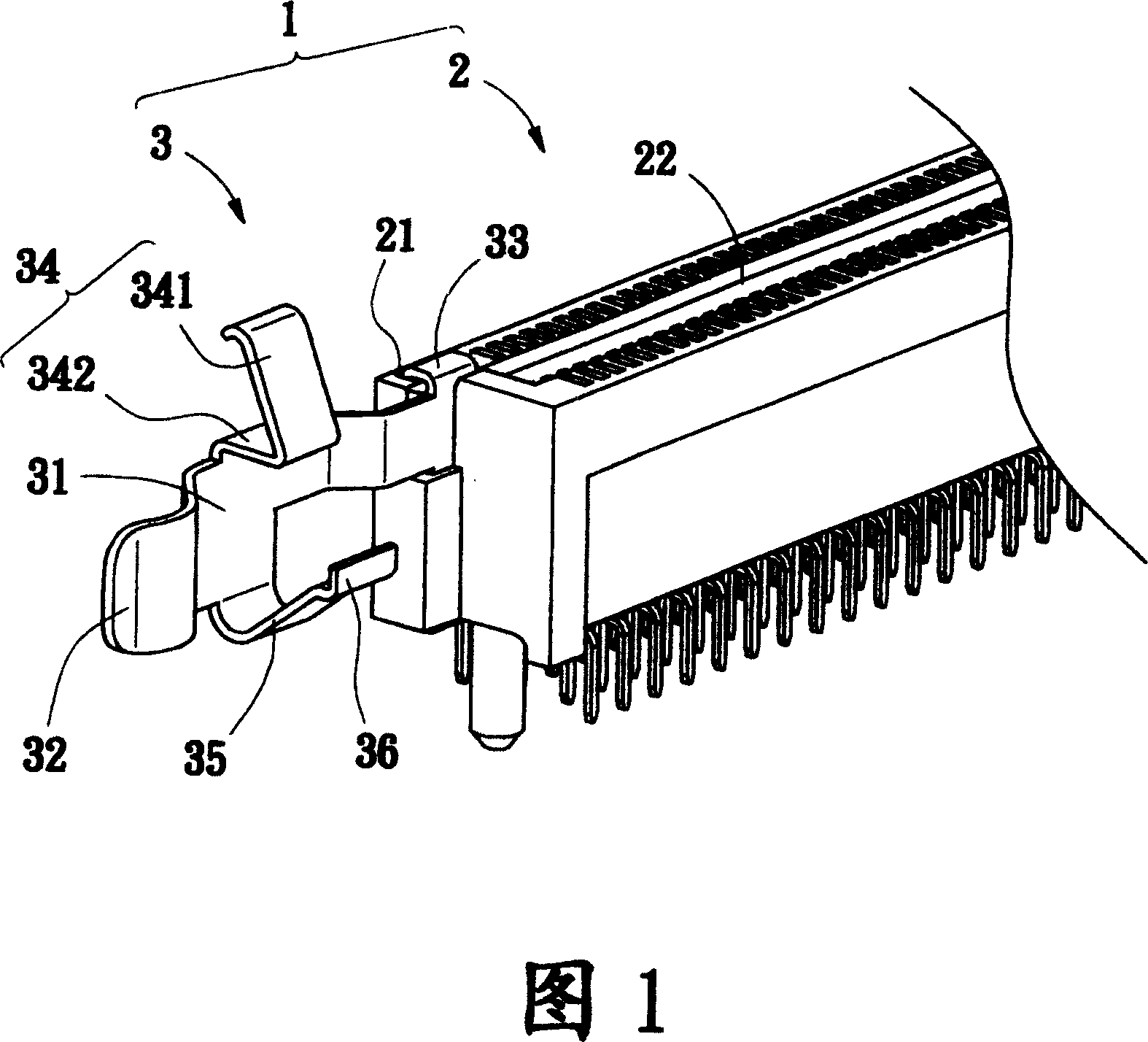
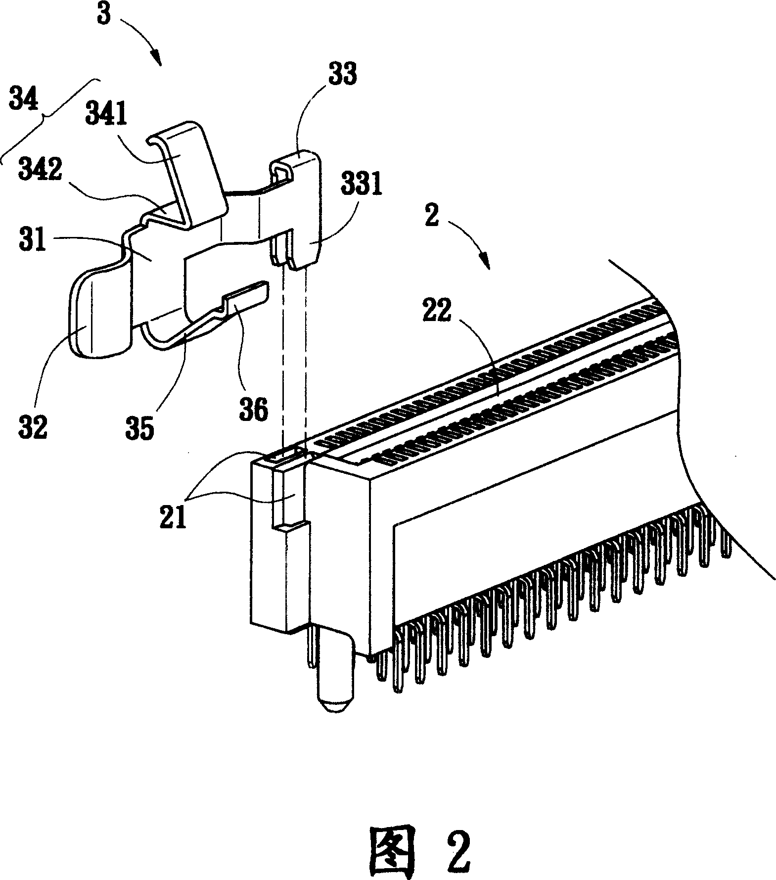
[0021] Please refer to the first embodiment of the adapter card connector 1 of the present invention shown in FIG. 1 and FIG. 2 , which includes a slot seat 2 and a buckle 3 .

[0022] The slot base 2 is combined on the top of the printed circuit board (not shown in the figure), and is provided with a slot 22 for the adapter card 9 (as shown in Figure 6) to be plugged and fixed. One end of the slot base 2 is provided with two a rectangular groove 21.

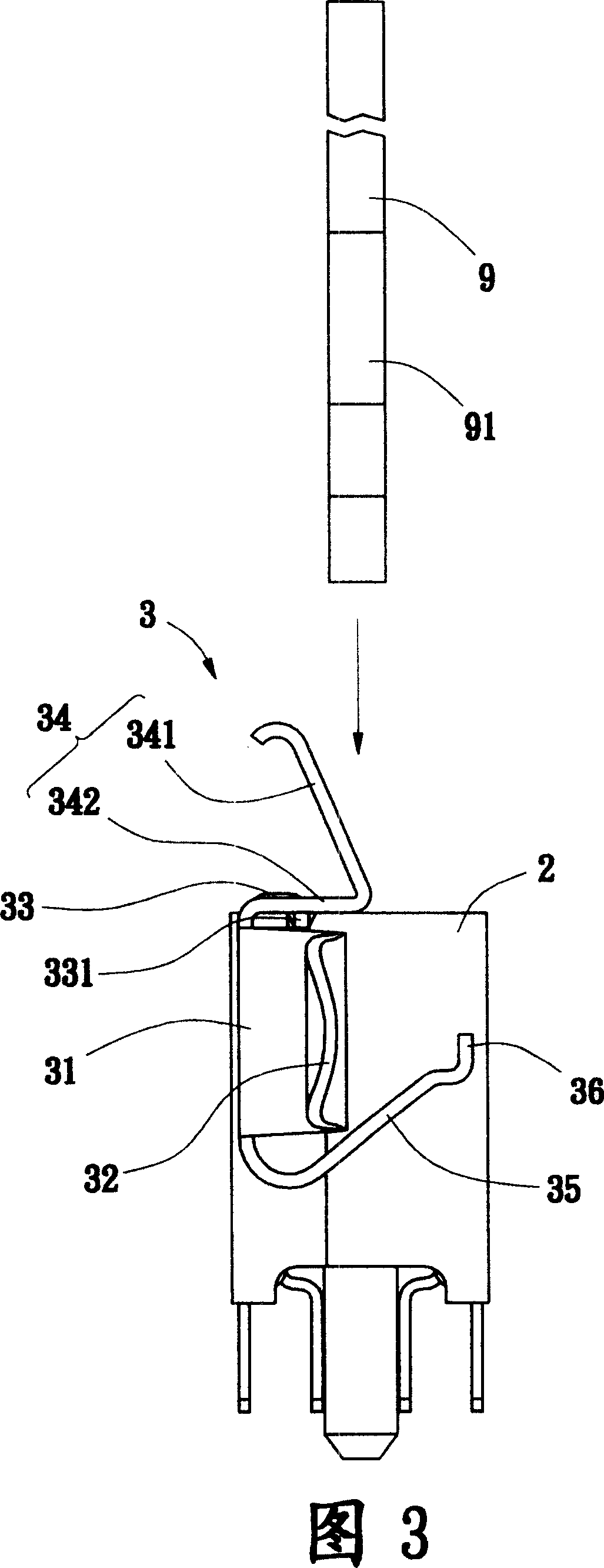
[0023] The buckle 3 is formed by bending a sheet metal body, which has an elastic portion 31, one end of the elastic portion 31 is provided with a dial portion 32, and the other end of the elastic portion 31 is provided with a joint portion 33, the joint portion 33 is in the shape of an inverted U, and has two elongated legs 331 extending downwards for insertion and fixing in the groove 21 of the socket base 2, so that the fastener 3 and the socket base 2 can be tightly combined. A hook portion 34 is arranged above the elastic ...


PUM


Abstract

This invention refers to a connector for adaptive card, which contains a socket and a snap fastener, one end of the snap fastener connected with socket, a inclined hook part set above the snap fastener to lead down the adaptive card to embed into the U-shaped open for fixing the connection of socket and adaptive card, an angle extended support set below the snap fastener for pushing to release the adaptive card from socket. Said invention is adaptive for adaptive card connector in computer printed circuit board.

Description

technical field [0001] The invention relates to an adapter card connector, in particular to an adapter card connector suitable for electrically connecting an adapter card and a printed circuit board of a computer host. Background technique [0002] Currently, several sockets are provided in a general computer mainframe to provide users with plugging in an adapter card to expand external devices or generate new functions. As shown in FIG. 11 , the conventional adapter card a is directly plugged into the slot c of the slot base b, and is electrically connected to the printed circuit board d under the slot base b. Since the gaps between the contact terminals e of the adapter card a are small, only a small amount of offset error can be tolerated when the adapter card a is in contact with the contact pieces f in the slot c. However, no matter when the computer is in use or in the process of installation and transportation, it is inevitable to generate vibrations of different siz...

Claims


Application Information

Patent Timeline
IPC IPC(8): H01R13/629
Inventor 范世青
Owner WONTEN TECH
Why Eureka
Try Eureka