Disk loader

A loading device and disk technology, which is applied in the recording of information on the disk, magnetic recording, instruments, etc., can solve the problems of excessive protrusion and unstable maintenance, and achieve the effect of avoiding disk contamination and simple structure

Inactive Publication Date: 2001-10-31
PANASONIC CORP
View PDF0 Cites 7 Cited by
  • Summary
  • Abstract
  • Description
  • Claims
  • Application Information

AI Technical Summary

Problems solved by technology

On the other hand, as shown in FIG. 3 , when the central hole of the small-diameter magnetic disk 2 protrudes outside the device main body 5 to make the disk easy to take out, the protrusion amount of the large-diameter magnetic disk 1 will be too large, and the retention under the protruding state will be difficult. Stablize

Method used


Image

  • Disk loader
  • Disk loader
  • Disk loader

Examples


Embodiment Construction

[0010] The best way to practice the invention

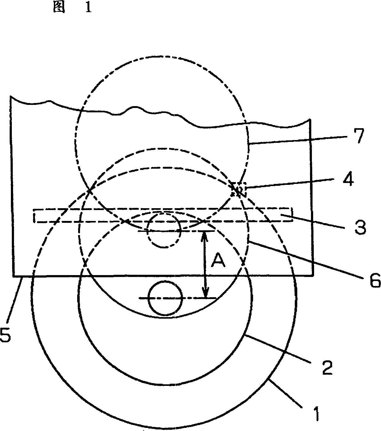
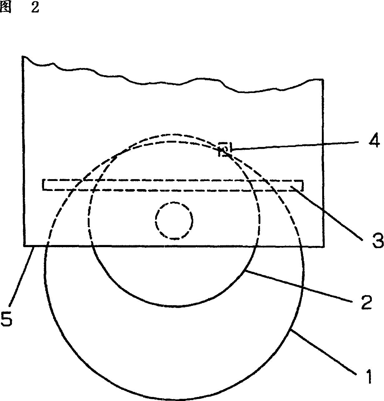
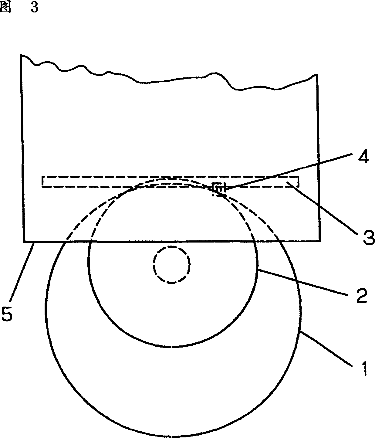
[0011] Fig. 1 shows a disk loading device of an embodiment of the present invention. The same parts as in Fig. 2 are given the same symbols. FIG. 1 shows a position 6 where the small-diameter magnetic disk 2 is ejected and a pass detection, and a position 7 where the small-diameter magnetic disk 2 is set on a turntable (not shown). In this device, when withdrawing from the large-diameter magnetic disk 1, when the passage of the large-diameter magnetic disk 1 is detected by the magnetic disk passing detection switch 4, the driving of the roller 3 will be stopped immediately, and the center hole will be used in the state where the central hole protrudes from the device main body 5. The disk stops and keeps it. And when withdrawing from the small-diameter disk 2, when the passing of the disk 2 is detected, the roller 3 is driven for a certain period of time instead of stopping immediately, and the driving of the roller 3 is stoppe...


PUM


Abstract

A disk loading apparatus is provided which stops disks, even if the disks have different diameters, when disk center holes have been ejected to the substantially same positions out of an apparatus body during the ejection. The disks can be pulled out without soiling a recording surface of the disk. One disk-pass detecting switch detects a pass of the last end of each disk and discriminates sizes of the disks. In addition, a rotation time of a roller after the detection of the pass is controlled depending on disk diameters.

Description

technical field [0001] The present invention relates to a disk loading device of a storage / playback device using a disk-shaped storage medium such as a CD (hereinafter referred to as a disk). Background technique [0002] Fig. 2 and Fig. 3 show the existing disk loading device. The device includes: a large-diameter disk 1, a small-diameter disk 2, a disk drive roller 3, a disk passing detection switch 4 for detecting the passage of the end of the disk passing on the switch, and a device main body 5. When withdrawing from the magnetic disk, the passing of the magnetic disk is detected by the magnetic disk through the detection switch 4, so that the magnetic disk is stopped at the position shown in Fig. 2 . [0003] Even when both the large-diameter (12 cm) magnetic disk 1 and the small-diameter (8 cm) magnetic disk 2 are used, they can be stopped by the same mechanism regardless of the difference in diameter. As shown in Figure 2, when the large-diameter magnetic disk 1 is ...

Claims


Application Information

Patent Timeline
Patent Type & Authority Applications(China)
IPC IPC(8): G11B17/051G11B17/04G11B19/12
CPCG11B17/0515G11B17/0404G11B17/04
Inventor 太田秀彦
Owner PANASONIC CORP
Why Eureka
Try Eureka