Movable armrest of passenger conveyer and armrest for passenger conveyer

A technology for passenger conveyors and handrails, applied in escalators, transportation and packaging, etc., can solve the problems of surrounding contamination and fluororesin fiber detachment, and achieve the effect of reducing resistance and preventing contamination

Active Publication Date: 2014-02-12
MITSUBISHI ELECTRIC BUILDING SOLUTIONS CORP
View PDF6 Cites 6 Cited by
  • Summary
  • Abstract
  • Description
  • Claims
  • Application Information

AI Technical Summary

Problems solved by technology

Therefore, if many fluororesin fibers are exposed on the inner surface of the moving handrail, there will be the following problems: the worn fluororesin fibers will come off, and the surroundings will be stained.

Method used


Image

  • Movable armrest of passenger conveyer and armrest for passenger conveyer
  • Movable armrest of passenger conveyer and armrest for passenger conveyer
  • Movable armrest of passenger conveyer and armrest for passenger conveyer

Examples


Embodiment approach 1

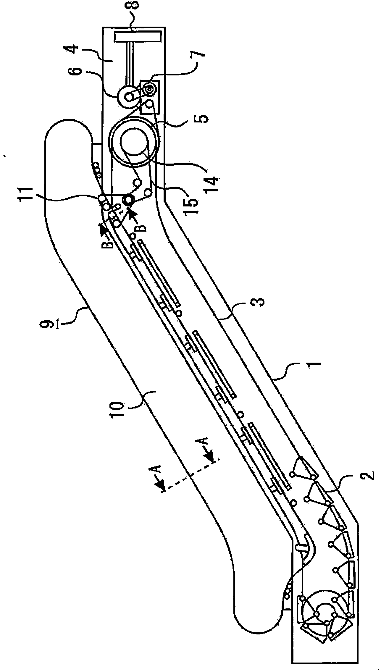
[0056] figure 1 It is a side view showing the overall structure of the passenger conveyor. Hereinafter, the structure of the escalator used when moving between upper and lower floors will be specifically explained. The description of other examples of the passenger conveyor, such as the structure of the moving sidewalk, is omitted.

[0057] in figure 1 Among them, number 1 is the truss of the escalator erected between the upper and lower floors. The truss 1 supports the dead weight and loading load of the escalator. Number 2 is the step used by passengers when they move between the upper and lower floors. The step 2 is connected to a ring-shaped step chain 3. In the machine room 4 installed on the upper part of the truss 1, the step chain 3 is wound around the step drive sprocket 5.

[0058] The number 6 is the drive motor, and the number 7 is the reducer. The drive motor 6 is used to drive the sprocket 5 for step drive and the like. The reducer 7 decelerates the output of th...

Embodiment approach 2

[0105] Figure 14 It is a figure which shows an example of the knitting method of the sliding cloth of the mobile handrail of Embodiment 2 of this invention.

[0106] in Figure 14 In the weaving method of the sliding cloth 21 shown, each lateral thread 23b passes through the back side of one longitudinal thread 24, and then continuously passes through the front side of the five longitudinal threads 24. The horizontal line 23b repeats this passage. For the vertical line 24, there are two passing methods relative to the horizontal line 23b. The first type longitudinal thread 24 passes through the front side of one transverse thread 23b, and then continuously passes through the back side of two transverse threads 23b. The first type longitudinal line 24 repeats this passage. The second type vertical thread 24 passes only the back side of the horizontal thread 23b. The first type longitudinal wires 24 and the second type longitudinal wires 24 are arranged alternately.

[0107] ...


PUM


Abstract

The invention provides a movable armrest of a passenger conveyer and an armrest for a passenger conveyer capable of reducing driving resistance greatly and preventing pollution of the peripheral fibers. The movable armrest (9) is provided with a main body resin part (17), a piece of base cloth (20), and a piece of sliding cloth (21). The main body resin part (17) is provided with a C-shaped cross section, and is in an annular shape. The base cloth (20) is disposed on the inner side surface of the main body resin part (17) along a long edge of the main body resin part (17). The sliding cloth (21) is disposed on the base cloth (20) by overlapping a part of the surface of the base cloth (20). In addition, the sliding cloth (21) is formed by being braided, and exposed parts (24a) of vertical lines (24) are not adjacent to each other. The predetermined fibers is used as the vertical lines (24), because the fibers are provided with the friction characteristics lower than the friction characteristics of the fibers of the base cloth (20), and the wear is easy to occur.

Description

Technical field [0001] The present invention relates to a mobile handrail used in a passenger conveyor and a handrail for a passenger conveyor intended for use in a passenger conveyor. Background technique [0002] In passenger conveyors called escalators or moving sidewalks, circular moving handrails with a C-shaped cross section are generally used. For safety, mobile handrails are used for grabbing by passengers on the steps. The moving handrail is driven in synchronization with the steps, and guides it to travel with the help of guide rails. [0003] In the passenger conveyor, the driving of the moving handrail and the guiding of travel are generally performed through the inner surface of the moving handrail. Therefore, the mobile handrail is required to have the following two functions on its inner surface: high friction characteristics (coefficient of friction) for generating sufficient driving force; and low friction characteristics (coefficient of friction) for reducing re...

Claims


Application Information

Patent Timeline
Patent Type & Authority Applications(China)
IPC IPC(8): B66B23/24
Inventor 本田武信
Owner MITSUBISHI ELECTRIC BUILDING SOLUTIONS CORP
Why Eureka
Try Eureka