Locking structure

A technology of locking structure and fastening part, applied in the direction of circuit layout, connecting components, quick action fasteners, etc.

Active Publication Date: 2007-07-18
YAZAKI CORP
View PDF7 Cites 0 Cited by
  • Summary
  • Abstract
  • Description
  • Claims
  • Application Information

AI Technical Summary

Problems solved by technology

[0006] However, as shown in FIG. 7, for example, a locking structure 100B in which an electrical component 140 is inserted and locked inside a box-shaped relay box 130, when the electrical component 140 is disassembled, the locking structure as described above should be 100A, it is very difficult to deform the locking piece 122 outward
[0007] That is, when dismounting electrical component 140 from relay box 130, for unlocking, for example, as shown in Figure 8 (A), tools such as screwdriver 101 are inserted between locking plate 122 and electrical component 140, as shown in Figure 8 ( As shown in B), use the front end of the screwdriver 101 to hold against the locking piece 122 and push it to the outside. In this state, it is necessary to pull the electrical component 140 upwards in order to make it cross the snapping piece 111. Cannot grasp the electrical component 140 and thus cannot remove it
[0008] In other words, while the locking piece 122 is stretched by the screwdriver 101, the electrical component 140 must be moved upward relative to the relay box 130, but since the electrical component 140 cannot be pushed up from the lower side, it is difficult for one person to operate it. is its problem

Method used


Image

  • Locking structure
  • Locking structure
  • Locking structure

Examples


Embodiment Construction

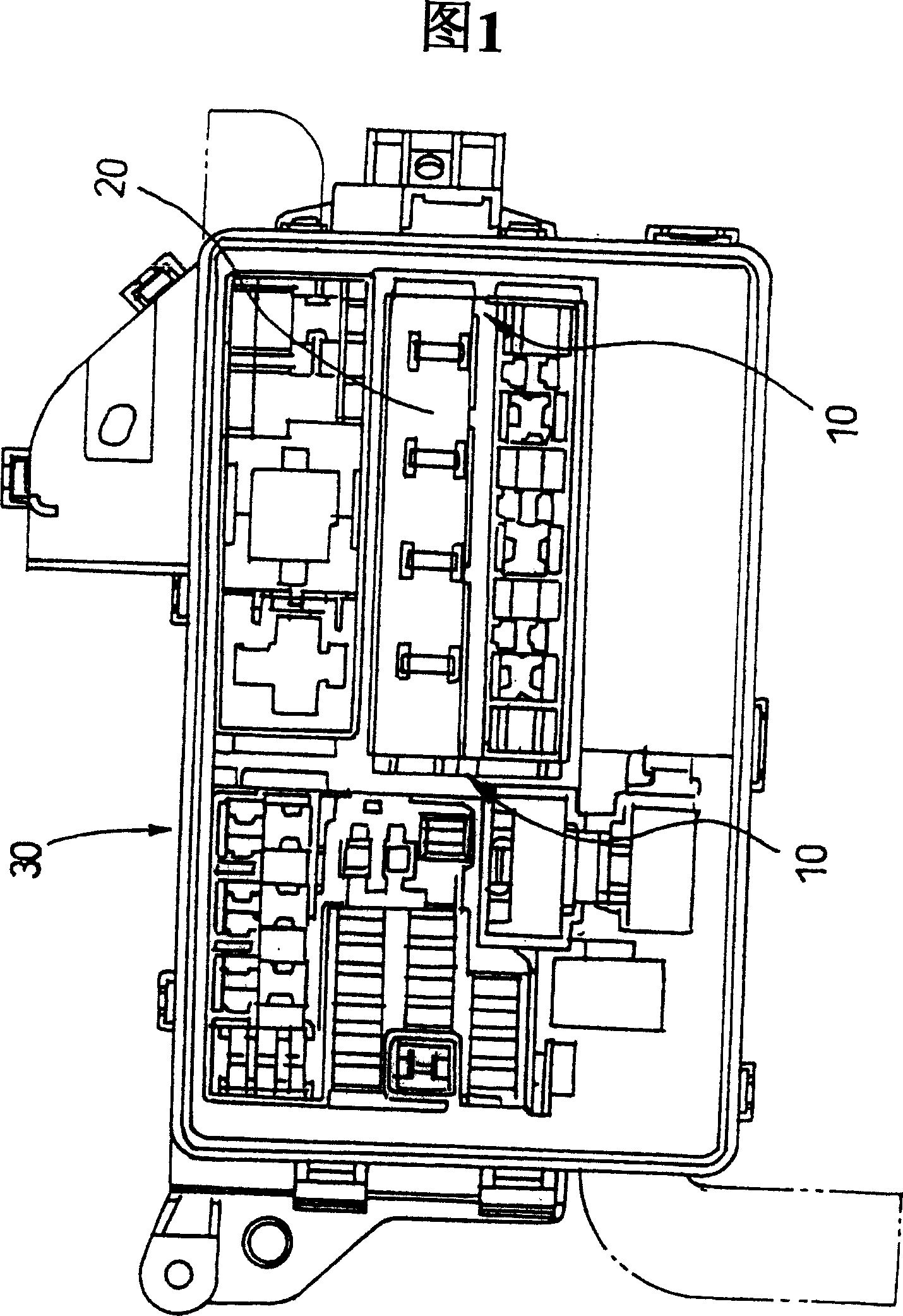
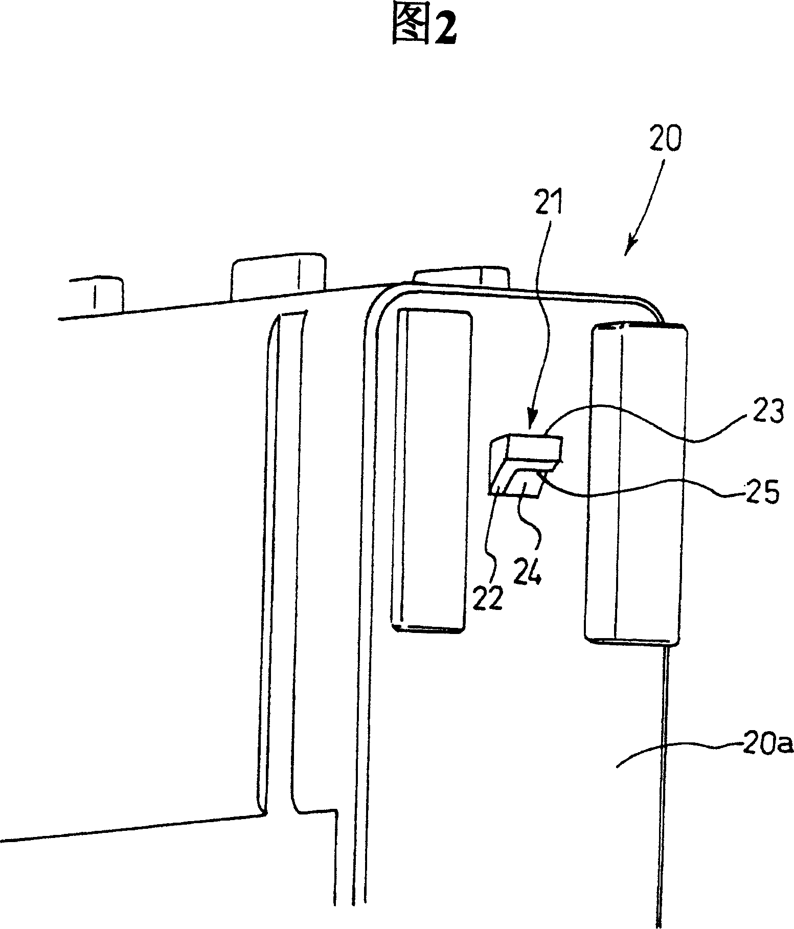
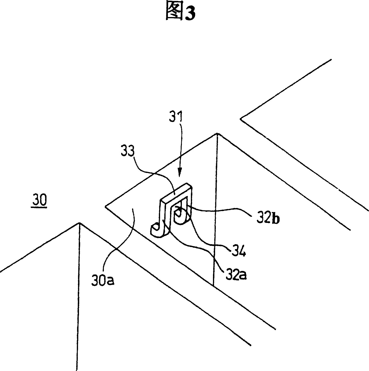
[0027] Hereinafter, embodiments of the present invention will be described in detail with reference to the drawings. Fig. 1 is a top view showing an example of a locking structure applicable to the present invention, Fig. 2 is a partial perspective view showing a buckling protrusion of the locking structure of the present invention, Fig. 3 is a perspective view showing a buckling part, Fig. 4 (A) to (C) are sectional views showing steps of unlocking and disassembling.

[0028] As shown in Figure 1, as the locking structure 10 of the embodiment of the present invention, box-type relay box 20 is installed in the inside of relay box 30, wherein, box-type relay box 20 is used as the relative one that makes relay and fuse modularization For one of the components, the relay box 30 serves as the other for accommodating various electrical components.

[0029] As shown in FIG. 2 , an engaging projection 21 is provided on an outer side wall 20 a of a box-type relay box 20 as one compon...


PUM


Abstract

Provided is a lock structure in which a locked state is easily canceled for detachment. A lock projection (21) provided in one member (20) is locked with a lock (31) provided in another member (30) to mutually lock the pair of confronted members (20, 30). A detaching jig (11) is then inserted between the lock projection (21) and the lock (31) to cancel the locked state, and the detaching jig (11) is hung on a wall (25) that is provided in the lock projection (21) to draw the one member (20) wherein the projection (21) is provided. Therefore, in such a lock structure (10), the lock projection (21) is detached from the lock (31) by the detaching jig (11) to cancel the locked state and to draw the lock projection (21), thereby solving a problem that it is conventionally difficult to detach the confronted members even by canceling the locked state.

Description

technical field [0001] The invention relates to a locking structure, in particular to a locking structure for fastening and locking a pair of opposite parts. Background technique [0002] Conventionally, for example, a locking structure in which a lid is attached to a box body and locked is known (see, for example, Patent Document 1). [0003] As shown in Figure 6, in this locking structure 100A, on the outer side wall of the box 110, there is a fastening piece 111 composed of a pair of protrusions; A pair of flexible arms 121 are arranged on it, and a locking piece 122 is arranged at the front end thereof. Like this, lid 120 is covered on box 110, and flexible arm 121 is deflected, thereby locking piece 122 is buckled with fastening piece 111 of box 110, thus, lid 120 and box 110 just are locked. up. [0004] On the other hand, in order to release the locked state, the locking piece 122 is held against the locking piece 122 with a dismounting tool such as the screwdriver...

Claims


Application Information

Patent Timeline
Patent Type & Authority Patents(China)
IPC IPC(8): H05K5/02G12B9/04F16B21/06F16B5/00F16B5/10H01H9/02H01H45/02H05K5/03H05K7/12
Inventor 前桥明美山田广明
Owner YAZAKI CORP
Why Eureka
Try Eureka