Electrostatic spinning tubular support collecting device and electrostatic spinning equipment

A collection device and electrospinning technology, applied in textile and papermaking, filament/thread forming, fiber processing, etc., can solve the problem of difficult to take out the tubular stent, avoid the original shape, stabilize the properties, and increase the desirability Effect

Active Publication Date: 2018-11-23
FOSHAN QINGZI PRECISION MEASUREMENT & CONTROL TECH
View PDF5 Cites 0 Cited by
  • Summary
  • Abstract
  • Description
  • Claims
  • Application Information

AI Technical Summary

Problems solved by technology

[0004] The purpose of the present invention is to overcome the deficiencies of the prior art and provide a collection device for electrospinning tubular stents, which uses a split structure tubular collector to collect tubular stents, and can easily take out the tubular stents without destroying the original shape of the tubular stents , to solve the problem that the tubular stent is difficult to remove

Method used


Image

  • Electrostatic spinning tubular support collecting device and electrostatic spinning equipment
  • Electrostatic spinning tubular support collecting device and electrostatic spinning equipment

Examples


Embodiment 1

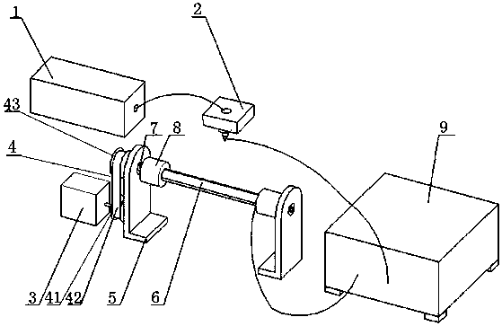
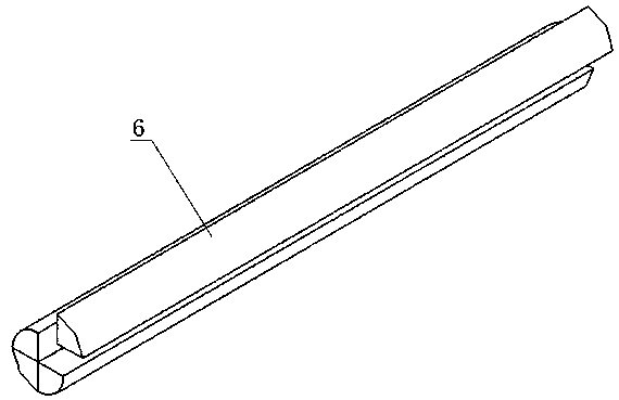
[0026] Such as Figure 1 to Figure 2 Shown is the first embodiment of the electrospinning tubular stent collection device of the present invention, comprising a support frame 5 and a collector rotatably connected to the support frame 5, the collector includes a split tubular structure 6 and a split-type structure for restraining The coupling 8 of the tubular structure 6, the coupling 8 is detachably connected to both ends of the split tubular structure 6; one end of the split tubular structure 6 is connected to a transmission mechanism, and the transmission mechanism is connected to Drive motor 3; the split tubular structure 6 is a conductive structure, a negative voltage is applied to the split tubular structure 6, and the fibers formed by the splitting of the charged jet released from the positive voltage end are directional suspended in the split tubular structure due to the action of the electric field force. Above structure 6.

[0027] During the implementation of this e...

Embodiment 2

[0033] Such as figure 1 Shown is an embodiment of the electrospinning device of the present invention, including the above-mentioned tubular support collection device, a DC power supply 9, a spinning needle 2 connected to the positive voltage terminal of the DC power supply 9, and a syringe pump communicated with the spinning needle 2 1. The tubular stent collection device is connected to the negative voltage terminal of the high-voltage power supply; the spinning needle 2 is arranged above the split tubular structure 6, and is used to inject a charged solution toward the tubular stent collection device.

[0034] In this embodiment, before electrospinning, the split tubular structure 6 is combined into a cylinder and fixed with a coupling 8, and the other end of the coupling 8 is installed on the transmission shaft 7 on both sides of the support frame 5, and then Turn on the power supply, the syringe pump 1 and the DC motor perform electrospinning, and the DC motor drives the ...


PUM

PropertyMeasurementUnit
angleaaaaaaaaaa

Abstract

The invention relates to the technical field of electrostatic spinning, and in particular to an electrostatic spinning tubular support collecting device and an electrostatic spinning device. The collecting device comprises a support frame and a collector rotatable connected with the support frame, the collector comprises a split tubular structure and a coupling used for restraining the split tubular structure, wherein the coupling is detachably connected to the two ends of the split tubular structure; one end of the split tubular structure is connected with a transmission mechanism, and the transmission mechanism is connected with a driving motor; the split tubular structure is of a conductive structure, a negative voltage is applied to the split tubular structure, and a fiber formed by the splitting of a charged jet released from a positive voltage end is directionally collected on the outer surface of the split tubular structure due to the action of an electric field force. The splittubular structure of the invention is a cylinder under the fixing of the coupling, the split tubular structure is split after the constraint of the coupling is loosened, a tubular bracket can be easily taken out without damaging the original appearance of the tubular bracket, and the problem that it is difficult to take out the tubular bracket is solved.

Description

technical field [0001] The invention relates to the technical field of electrospinning, and more specifically, to an electrospinning tubular support collection device and an electrospinning device. Background technique [0002] Cardiovascular disease is one of the main causes of human death, especially coronary artery disease accounts for 53% of the total mortality of cardiovascular disease, surgical replacement or bypass grafting is the main means of treatment of coronary artery and other diseases. Autologous blood vessels and artificial synthetic blood vessels are the main clinical vascular grafts, but the sources of autologous blood vessels are limited, and it is difficult to meet clinical needs. Vascular tissue engineering technology provides a new source of small-diameter vascular grafts. The idea is to use the combined culture of vascular cells and degradable scaffolds to construct biologically active and functional small-diameter vascular substitutes. Degradable scaf...

Claims


Application Information

Patent Timeline
Patent Type & Authority Applications(China)
IPC IPC(8): D01D5/00
CPCD01D5/0061D01D5/0076
Inventor 许国杰王晗梁烽余佳鸿林晓峰曾俊陈新度辛正一曾景华庞应龙
Owner FOSHAN QINGZI PRECISION MEASUREMENT & CONTROL TECH
Why Eureka
Try Eureka