
Valve device

A technology of valve device and driving device, which is applied in the direction of valve device, valve operation/release device, valve details, etc., and can solve the problems of difficult valve body opening and closing stability control, etc.

Inactive Publication Date: 2007-08-01
SANKYO SEIKI MFG CO LTD
View PDF7 Cites 0 Cited by
  • Summary
  • Abstract
  • Description
  • Claims
  • Application Information

AI Technical Summary

Problems solved by technology

Especially when the fluid pressure is high, the required torque of the motor drive part increases, and if a motor drive part with a large turning torque is used, it is difficult to stably control the opening and closing of the valve body

Method used


Image

  • Valve device
  • Valve device
  • Valve device

Examples


Embodiment Construction

[0026] The best mode for carrying out the present invention will be described below with reference to the accompanying drawings.

[0027] [the whole frame]

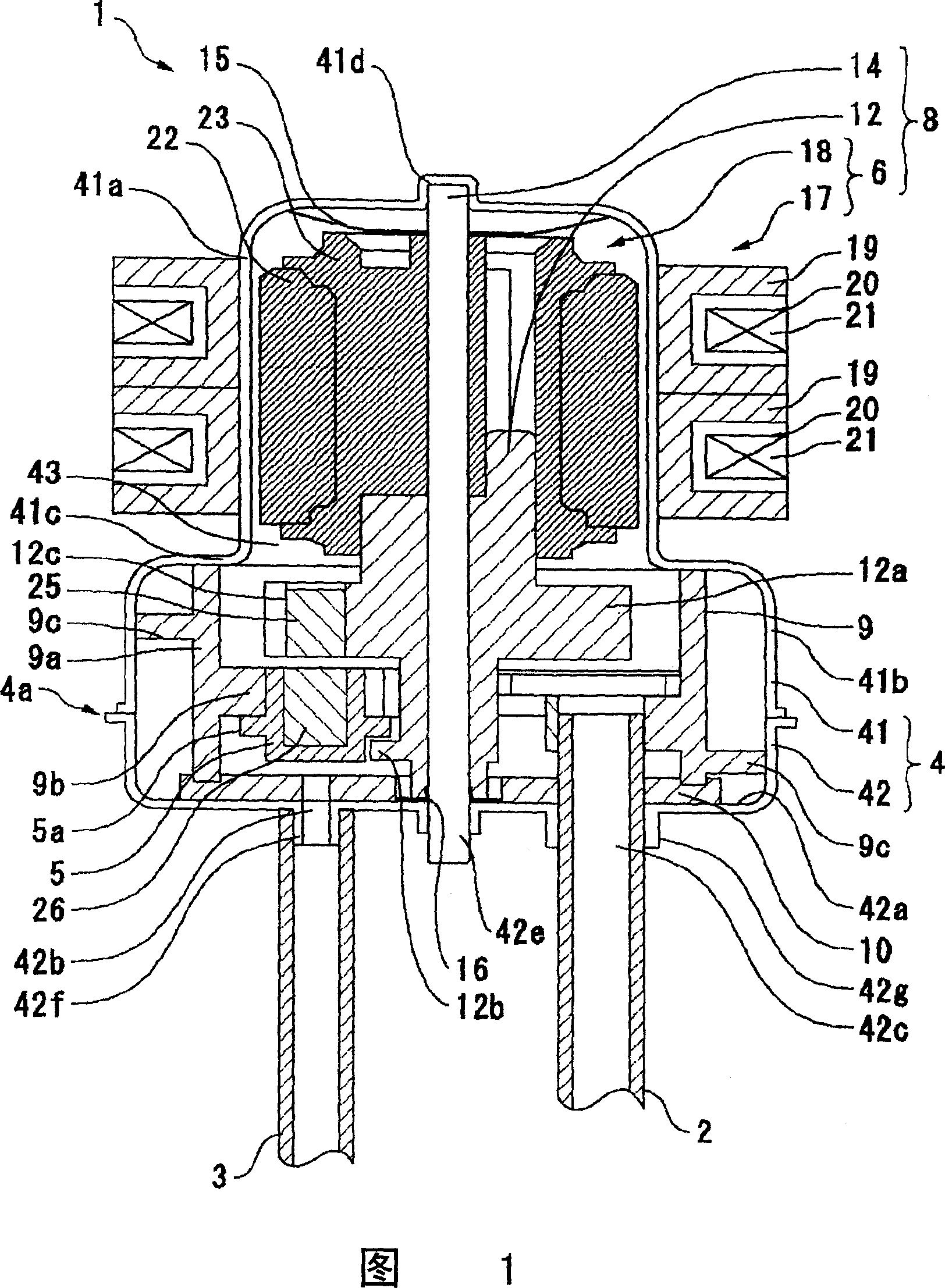
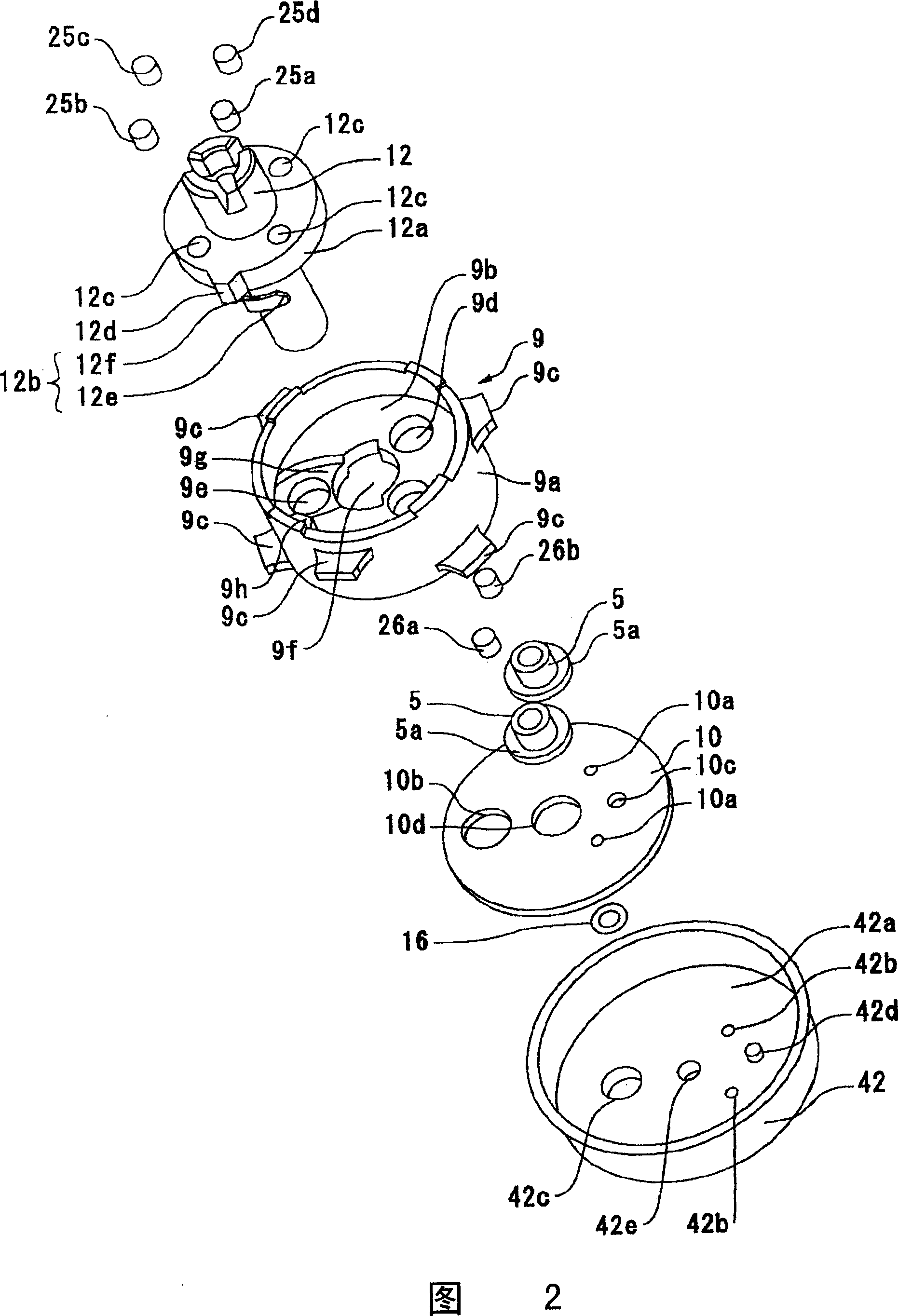
[0028] Fig. 1 is a longitudinal sectional view showing a valve device according to an embodiment of the present invention, showing a state where a valve body is in an open position. Fig. 2 is an exploded perspective view of main parts of the valve device shown in Fig. 1 .

[0029] The valve device 1 applicable to the present invention is, for example, a device for controlling the temperature of a refrigerating room passing through the flow path by opening and closing the refrigerant flow path of a refrigerator, and has an inflow pipe for connecting the refrigerant flowing in 2 and the two outflow pipes 3 that flow out of the refrigerant, and the body shell 4 that guides the refrigerant flowing in from the inflow pipe 2 to the fluid flow path 43 of the outflow pipe 3 is formed inside; in order to open and close the body c...


PUM


Abstract

A valve device includes a main body case to which an inflow pipe and an outflow pipe are connected, a valve element which is disposed inside of the main body case to open or close an outflow aperture part of the main body case, a motor for moving the valve element in an open direction and a closed direction, a valve element drive means which is driven by the motor and includes a rotary member rotated by the motor and a rotation side permanent magnet mounted in the rotary member, a valve element side permanent magnet mounted in the valve element, and a holding member which movably holds the valve element. The valve element is urged in the open direction or the closed direction by a magnetic attractive force or a magnetic repulsive force generated between the rotation side permanent magnet and the valve element side permanent magnet.

Description

technical field [0001] The present invention relates to a valve device that operates a valve body to open and close flow paths of various fluids, and particularly relates to a valve body opening and closing mechanism of the valve device. Background technique [0002] As a valve device for opening and closing the flow paths of various fluids such as refrigerants in refrigerators and air conditioners, and controlling the temperature of a room passing through the flow paths, a valve device having the following structure is known. The inflow pipe of the inflow pipe and the outflow pipe of the outflow fluid are formed inside the body shell that guides the fluid flowing in from the inflow pipe to the fluid flow path of the outflow pipe; in order to open and close the outflow opening of the body shell connected to the outflow pipe And the valve body arranged inside the main body casing; and the valve body driving device which has a motor drive part and drives the valve body to open...

Claims


Application Information

Patent Timeline
Patent Type & Authority Patents(China)
IPC IPC(8): F16K31/02F16K31/06F16K11/072F16K31/04F16K31/08
CPCF16K31/042F16K31/045Y10T137/86863F16K31/06F16K31/02
Inventor 小泽滋原哲彦
Owner SANKYO SEIKI MFG CO LTD
Learn More