
Working method of internal-combustion engine, control device and internal-combustion engine

A working method and technology of a control device are applied to the work of an automobile internal combustion engine. , In the field of internal combustion engine control devices, it can solve problems such as no consideration

Inactive Publication Date: 2008-05-14
ROBERT BOSCH GMBH
View PDF7 Cites 0 Cited by
  • Summary
  • Abstract
  • Description
  • Claims
  • Application Information

AI Technical Summary

Problems solved by technology

Other properties of the internal combustion engine that are most affected by switching between different fuel types are not considered in this prior art document

Method used


Image

  • Working method of internal-combustion engine, control device and internal-combustion engine
  • Working method of internal-combustion engine, control device and internal-combustion engine
  • Working method of internal-combustion engine, control device and internal-combustion engine

Examples


Embodiment Construction

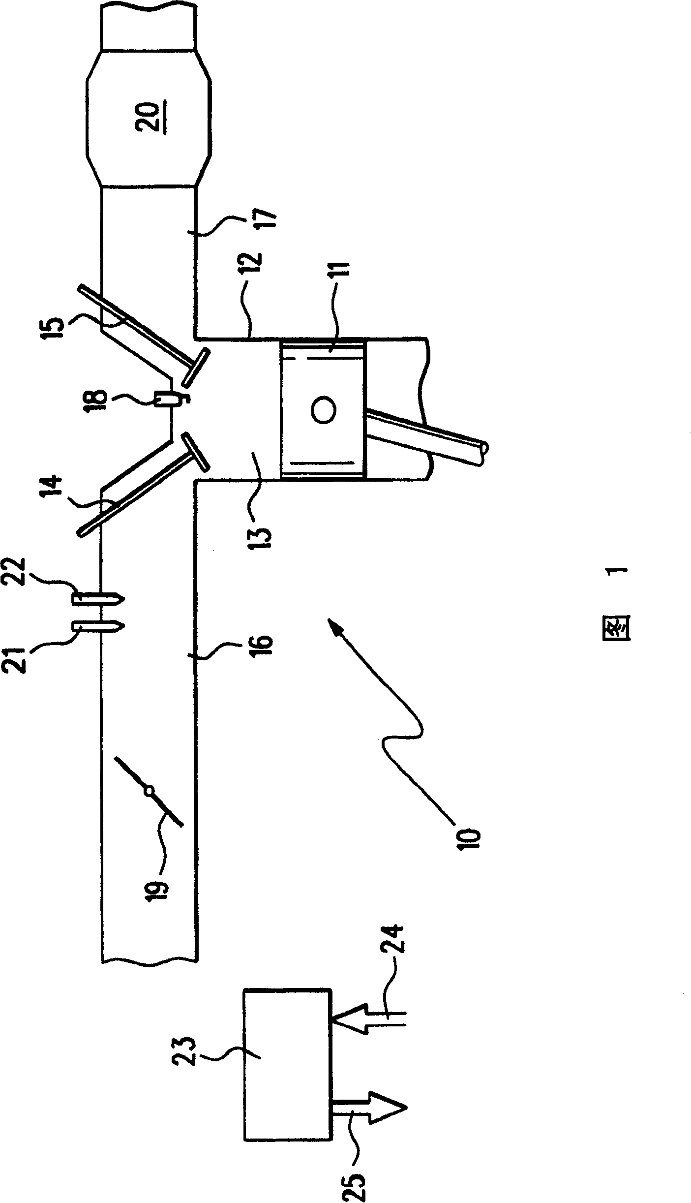
[0024] FIG. 1 shows a motor vehicle internal combustion engine 10 in which a piston 11 can move back and forth in a cylinder 12 . The cylinder 12 has a combustion chamber 13 which is delimited by a piston 11 , an intake valve 14 and an exhaust valve 15 . An intake pipe 16 is connected to the intake valve 14 , and an exhaust pipe 17 is connected to the exhaust valve 15 . The combustion chamber 13 also has a spark plug 18 .

[0025] Arranged in the intake manifold 16 is a throttle valve 19 via which air can be supplied to the combustion chamber 13 . The input air flow is related to the opening degree of the throttle valve 19 . A catalytic converter 20 is contained in the exhaust pipe 17 .

[0026] Between the throttle valve 19 and the intake valve 14, there are two fuel injection nozzles 21, 22 in the intake pipe 16. The first fuel injector 21 is used to inject fuel, especially gasoline. The second fuel injection nozzle 22 is used for injecting gas, especially propane or na...


PUM


Abstract

An operating process for a combustion engine, especially for a motor vehicle, which can switch between gaseous and liquid fuel injection systems prevents changes in torque during fuel switching by influencing the operational parameters during the changeover. Independent claims are also included for the following: (a) a combustion engine, especially for a motor vehicle as above; (b) a computer command program for the above;and (c) a control unit for the combustion engine

Description

technical field [0001] The invention relates to a working method of an internal combustion engine, in particular to a working method of an automobile internal combustion engine. The invention also relates to a corresponding internal combustion engine control device and a corresponding internal combustion engine. Background technique [0002] A motor vehicle internal combustion engine operating with two different fuels is known from DE 19922748 A1. Switching between the two fuels is based on the emissions produced. In particular, emissions of harmful substances can be reduced by this conversion. [0003] Only the emissions of internal combustion engines are considered in DE 19922748 A1. Other properties of the internal combustion engine which are most affected by switching between different fuel types are not considered in this prior art document. Contents of the invention [0004] The object of the present invention is to provide a method for operating an internal comb...

Claims


Application Information

Patent Timeline
Patent Type & Authority Patents(China)
IPC IPC(8): F02D41/30F02D19/06F02D37/02F02D41/00F02D41/14F02D41/34
CPCF02D19/0692F02D41/0027F02D41/0025F02D19/0642F02D37/02F02D41/1497F02D19/061F02D19/081F02D41/008F02D41/123F02D2250/21Y02T10/30
Inventor S·施奈德
Owner ROBERT BOSCH GMBH
Learn More