A method for implementing bandwidth sharing architecture of virtual user ring network

A technology of bandwidth sharing and virtual users, applied in the direction of ring network, transmission system, digital transmission system, etc., can solve the problems of wasting bandwidth resources, unable to make full use of ring bandwidth resources, lack of ring network fairness algorithm, etc., to improve network bandwidth The effect of usage

Inactive Publication Date: 2007-08-22
SHENZHEN HUAWEI TECHNOLOGIES SOFTWARE CO LTD
View PDF3 Cites 0 Cited by
  • Summary
  • Abstract
  • Description
  • Claims
  • Application Information

AI Technical Summary

Problems solved by technology

The use of tokens allows at most one node to access the network at any one time, and some methods are needed to ensure that there is only one token on the ring, so that as long as a certain section of the ring has data packets being transmitted, the rest of the ring The segment can only be idle, which causes a great waste of bandwidth resources
[0003] Although the ring formed by Layer 2 switching can make each node share the bandwidth of the ring, when bandwidth competition occurs among the nodes on the ring, there is no effective ring network fairness algorithm, and the actual bandwidth of each node is difficult to guarantee.
If the way of configuring node bandwidth is adopted, although it can increase the fairness of each node, it cannot make full use of the bandwidth resources of the ring
Moreover, when a physical ring can be regarded as composed of several virtual sub-rings, there is no effective ring network fairness algorithm to share the ring network bandwidth between the nodes inside the sub-ring and between sub-rings.
[0004] The purpose of the present invention is to solve the above-mentioned ring network bandwidth sharing problem among the nodes inside the sub-ring and between sub-rings, and to ensure the fairness between them to the greatest extent, so as to provide a virtual Realization method of bandwidth sharing system of user ring network

Method used


Image

  • A method for implementing bandwidth sharing architecture of virtual user ring network
  • A method for implementing bandwidth sharing architecture of virtual user ring network
  • A method for implementing bandwidth sharing architecture of virtual user ring network

Examples


Embodiment approach

[0019] The present invention will be further described below in conjunction with drawings and embodiments.

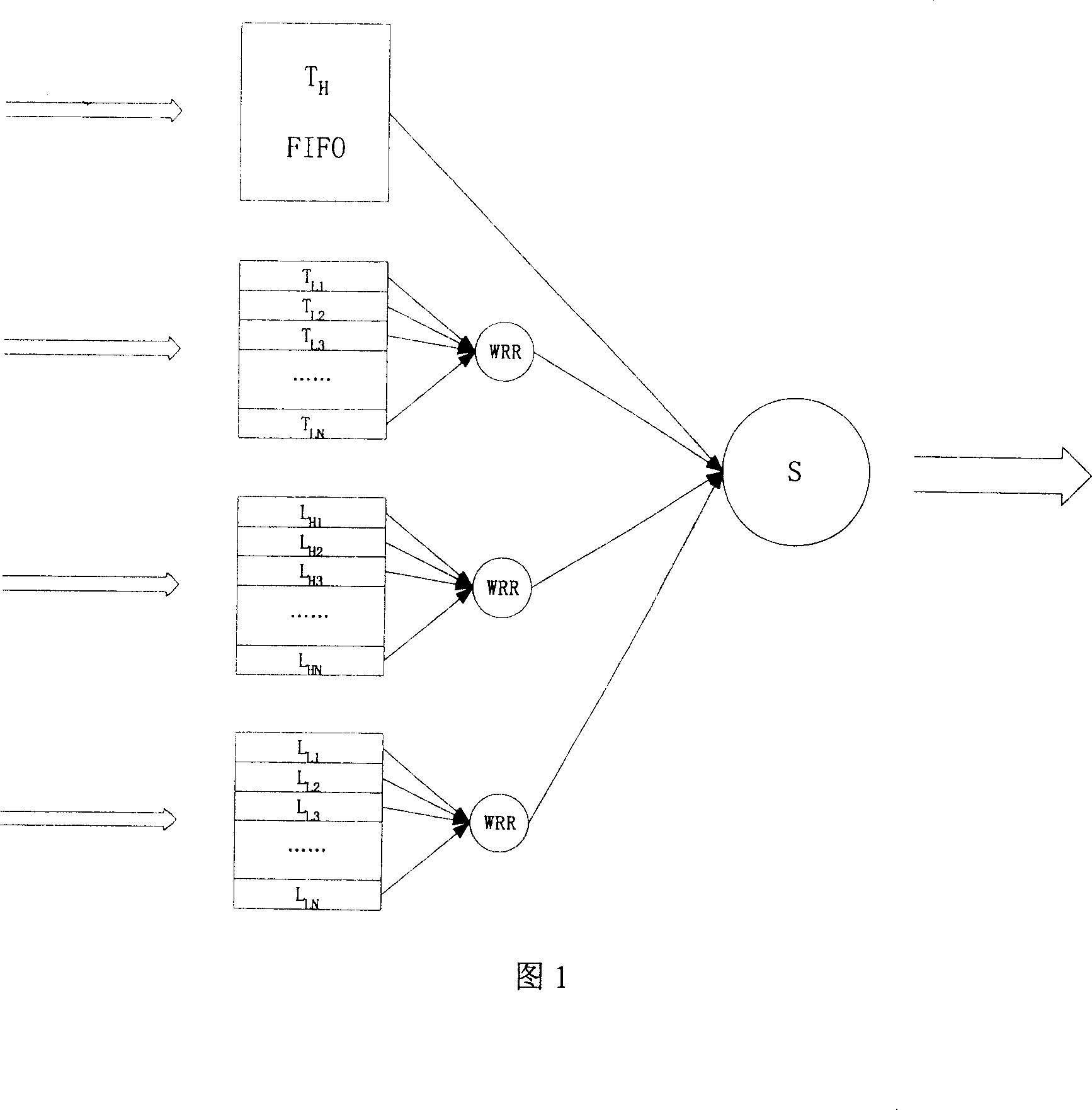
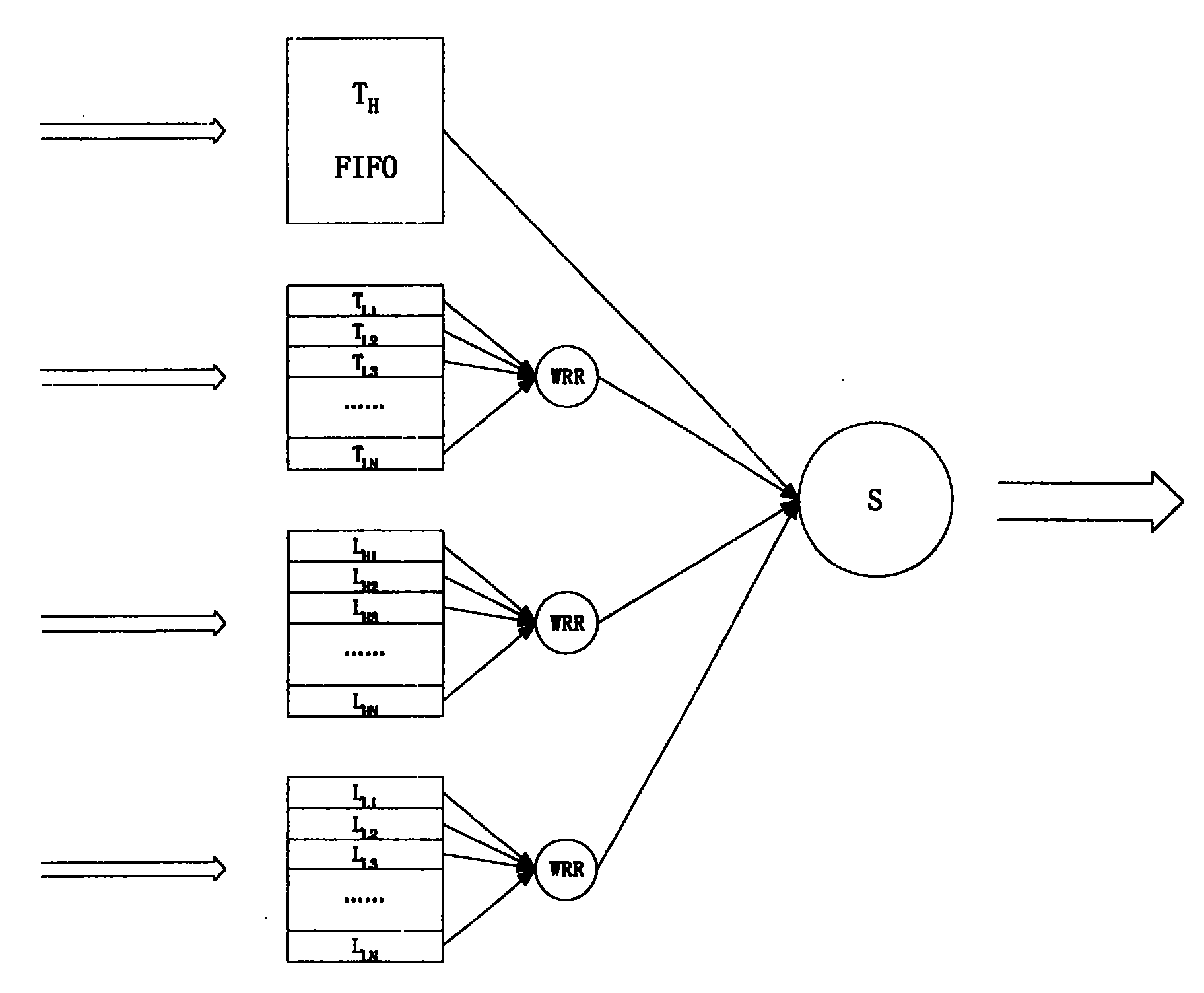
[0020] Figure 1 shows a queue scheduling block diagram of a node. Among them, T H Indicates forwarding high-priority packets, T L Indicates forwarding low-priority packets, L H Indicates local high-priority packets, L L Indicates local low-priority packets.

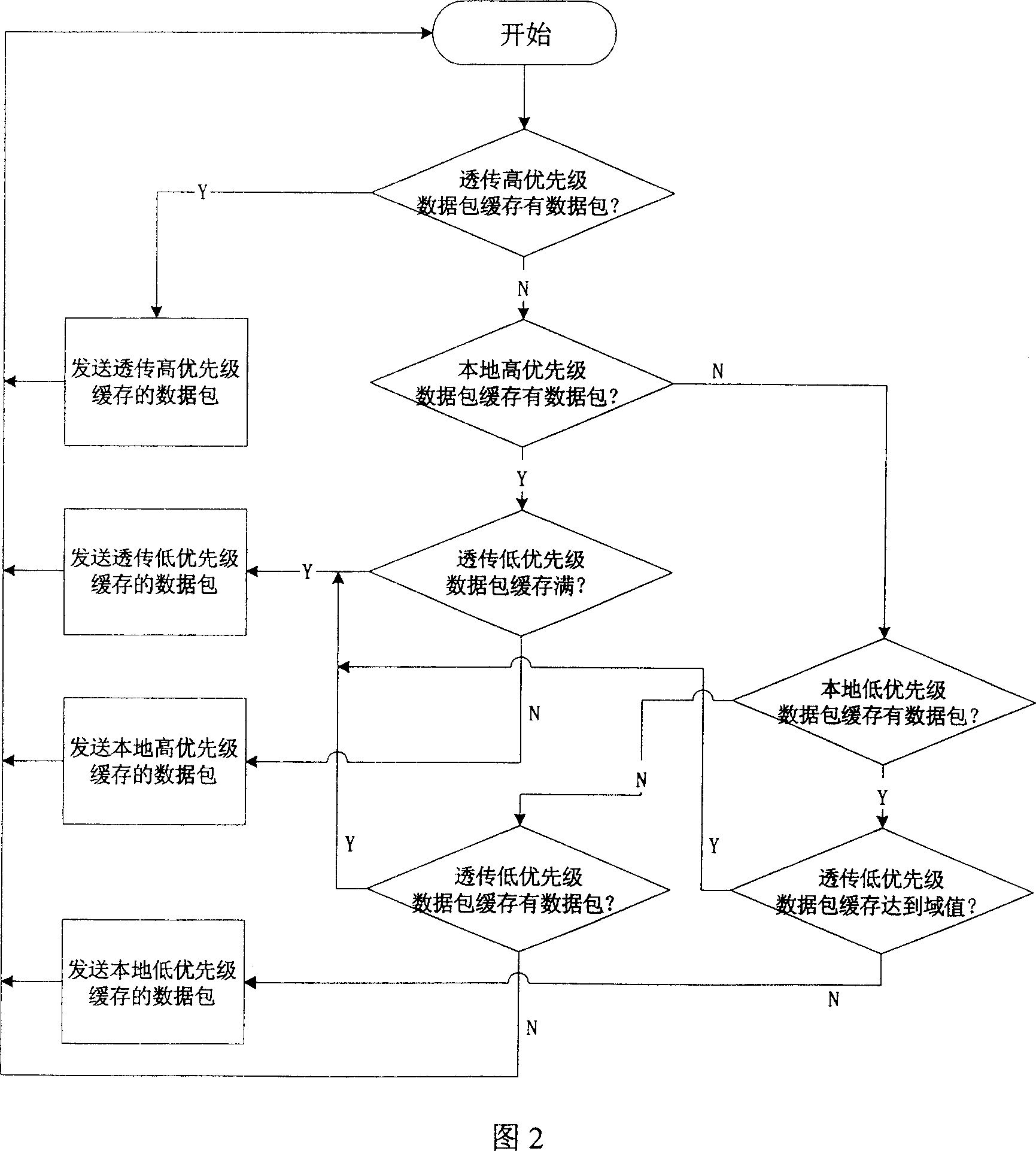
[0021] FIG. 2 shows a flow chart of a node's sending message processing.

[0022] In Figure 1, each station has four types of queues: forwarding high-priority message queues, forwarding low-priority message queues, local high-priority message queues, and local low-priority message queues. Each type of queue is subdivided according to the user (except for the forwarded high-priority message queue, because it can be sent out quickly). Firstly, weighted round-robin scheduling is performed on each type of queue, and then fair scheduling is performed on the four types of queues.

[0023] FIG. 2 is a flow chart of ...


PUM


Abstract

The invention relates to allocation method of bandwidth of the communication network. When a user accesses each of the nodes on the circle, and they need interlink each other, we can think that this node make up of a virtual sub-ring that means the whole physical circle makes up of many virtual sub-rings. As well as, according to the circle net equity algorithm the bandwidth can be share between each of the nodes in the inner part of the sub-ring and the sub-ring and sub-ring.

Description

Technical field: [0001] The invention relates to a method for allocating communication network bandwidth. Background technique: [0002] In multi-access communication systems, such as enterprise networks, metropolitan area networks, and wide area networks, most of these networks use ring topology, and ring networks such as FDDI networks or token ring networks rely on tokens on the ring. to gain access to network resources. The use of tokens allows at most one node to access the network at any one time, and some methods are needed to ensure that there is only one token on the ring, so that as long as a certain section of the ring has data packets being transmitted, the rest of the ring The segment can only be idle, which causes a great waste of bandwidth resources. [0003] Although the ring formed by Layer 2 switching can make each node share the bandwidth of the ring, when bandwidth competition occurs among the nodes on the ring, there is no effective ring network fairnes...

Claims


Application Information

Patent Timeline
Patent Type & Authority Patents(China)
IPC IPC(8): H04L12/42H04L12/24H04Q3/64H04Q3/545
Inventor 徐松余
Owner SHENZHEN HUAWEI TECHNOLOGIES SOFTWARE CO LTD
Why Eureka
Try Eureka