
Head-light

A technology for headlamps and light sources, applied in the field of headlamps, can solve the problems of difficulty in forming a luminosity distribution pattern, low efficiency, etc.

Inactive Publication Date: 2002-02-27
CATEYE
View PDF0 Cites 3 Cited by
  • Summary
  • Abstract
  • Description
  • Claims
  • Application Information

AI Technical Summary

Problems solved by technology

If you rely on this manual method, the efficiency is very low, and the photometric distribution mode is difficult to form the desired photometric distribution mode.

Method used


Image

  • Head-light
  • Head-light
  • Head-light

Examples


Embodiment Construction

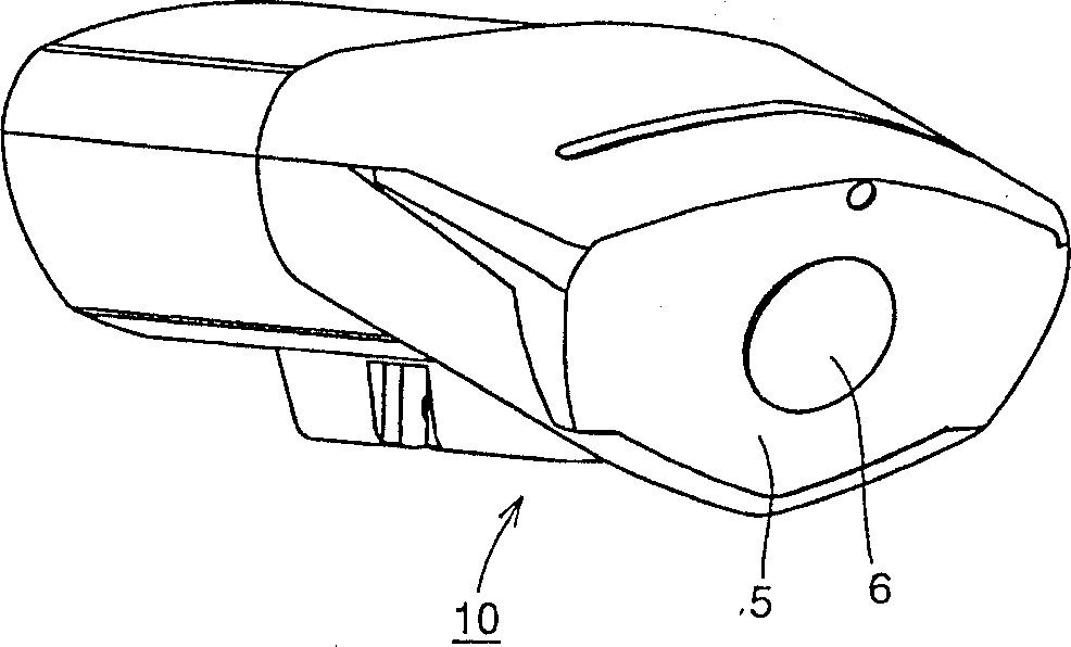
[0033] Embodiments of the present invention will be described below using the drawings. figure 1 It is a perspective view of the appearance of a headlight according to an embodiment of the present invention. The headlight 10 is mounted on a bicycle, and projects light forward from a front lens 5 including a center lens 6 .

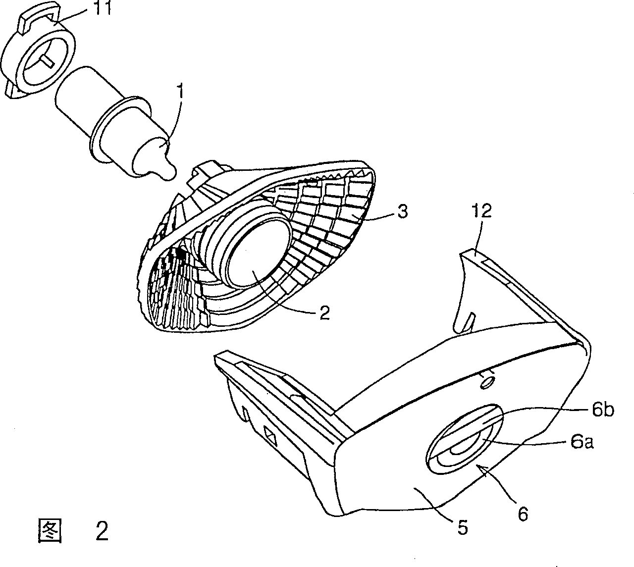
[0034] Figure 2 is figure 1 An exploded view of part of the headlamp. The front lens 5 includes a central lens 6 and is integrally formed with a mounting portion 12 for mounting the front lens on a frame (not shown). The central lens 6 is divided into a strip lens 6b and a concentric circular lens 6a.

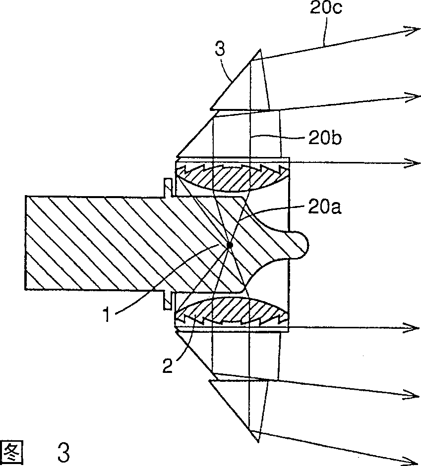
[0035] Behind the above-mentioned front lens, there are provided a polygon mirror 3 and a cylindrical convex lens 2 surrounded by the polygon mirror. In order to make this cylindrical convex lens function as a convex lens with a very thin thickness, a Fresnel lens is used. In the Fresnel lens 2, a light source 1 emitting light from a tungsten wire (not...


PUM


Abstract

A headlight allowing easy adjustment of a delicate light distribution pattern during manufacturing is provided. The headlight includes a light source (1), a reflector (3) surrounding the light source from its backside to reflect light incident from the light source frontward, and a front lens (5) located in front of the light source and the reflector. The front lens is provided with at least two portions (6a, 6b) different in light transmission characteristic from each other.

Description

technical field [0001] The present invention relates to a headlamp, and more particularly, to a headlamp capable of easily adjusting a fine luminosity distribution pattern in manufacture. Background technique [0002] The structure of the previous headlights is as follows: [0003] (a) The light emitted from the tungsten wire placed near the focal point of the paraboloid diffuses in all directions and is reflected by the parabolic mirror to form parallel rays. The parallel rays form the desired light intensity distribution pattern by the front lens. [0004] (b) The light emitted by the tungsten wire is projected forward through the polygon mirror to form the desired light intensity distribution pattern. The front lens only acts as a cover. Each part of this polygon mirror reflects the light emitted from the tungsten wire in a specific direction, and the size and angle of each part are set so that the desired light intensity distribution mode can be...

Claims


Application Information

Patent Timeline
Patent Type & Authority Applications(China)
IPC IPC(8): F21S8/10F21S8/12F21V5/00F21V7/09F21V13/00F21V13/04F21W101/10F21Y101/00
CPCF21S48/1233F21S48/24F21S48/2212F21S41/28F21S43/26F21S43/40
Inventor 小路正央
Owner CATEYE
Learn More