Cordless electrical appliances

A cordless electric and cordless electric connector technology, applied in the field of cordless liquid heating container, can solve the problems of increased weight, increased cost, space occupied by batteries, etc.

Inactive Publication Date: 2002-04-10
STRIX LTD
View PDF5 Cites 29 Cited by
  • Summary
  • Abstract
  • Description
  • Claims
  • Application Information

AI Technical Summary

Problems solved by technology

However, this solution is not suitable for a number of reasons - the battery would take up valuable space, add extra weight and be replaced by the user when worn out
More importantly, it significantly increases the cost due to the need to provide suitable containers, terminals, etc.

Method used


Image

  • Cordless electrical appliances
  • Cordless electrical appliances
  • Cordless electrical appliances

Examples


Embodiment Construction

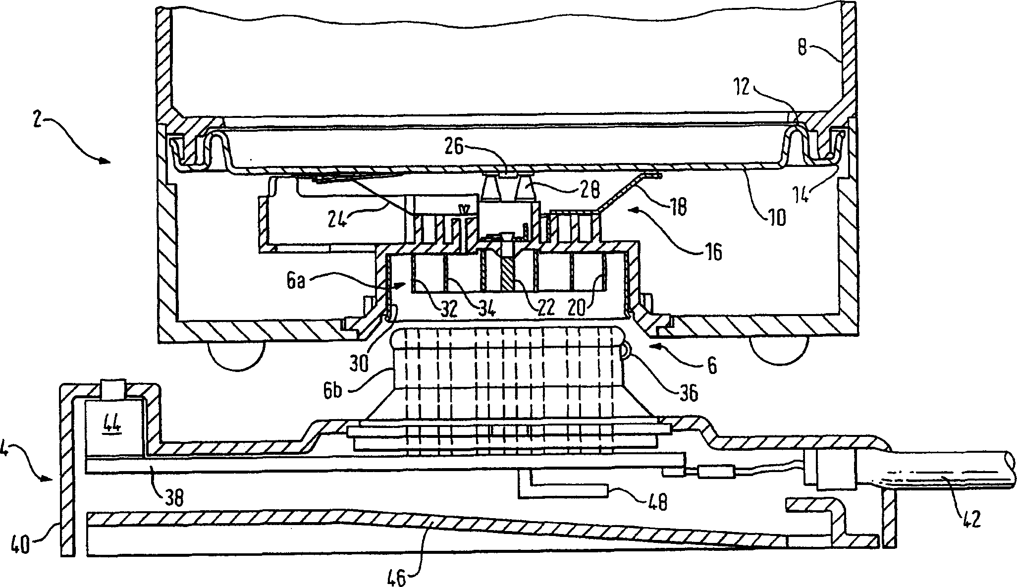
[0080] turn first figure 1 , the lower part of the cordless liquid heating device is shown in cross section. The device generally comprises a container part 2 and a base part 4 . The electrical connection between the two parts is provided by a 360° cordless connector generally indicated by the reference number 6 , which allows the container part 2 to be placed and operated in any angular orientation relative to the base 4 . However, the base portion 6b of the connector is not sectioned for clarity.

[0081] Returning to the container part 2 , it has a plastic container wall 8 with an open lower end closed by a thick film printed heater 10 . The base plate of the thick film heater 10 has a reinforcing flange 12 at its periphery and is sealed to the vessel wall 8 by channel members 14 deformable to grip the depnding portion of the vessel wall. Further details of this structure are given in GB-A-2301434.

[0082] An element interface unit, generally indicated at 16, is dispos...


PUM


Abstract

A cordless electrical appliance has thermal sensing means in the appliance part and an electronic control in the base part. Two thermistors are shown for the thermal sensing means to monitor for liquid temperature during normal operation and also for dry switch-on. Also disclosed is a multi-pole 360-degree cordless connector providing two extra poles which can allow electrical connection to be made to the thermal sensing means.

Description

technical field [0001] The present invention relates to a cordless electrical device and in particular, but not exclusively, to a cordless liquid heating vessel. Background technique [0002] Currently, the use and benefits of cordless electrical connectors for powering the heating elements of the appliances in household appliances such as kettles, coffee percolators and irons are well known. More recently, 360° cordless connectors have been introduced, an example of which is disclosed in WO 95 / 08204. This type of connector is rapidly gaining popularity in the market. [0003] Although there have been many recent innovations in the field of liquid heating vessels, especially related to the introduction of thick film heaters, the functionality of the cordless connection system remains the same - that is, for a cordless base, electrical power is supplied to the vessel and a controller inside the vessel controls the Power supply for heating elements. ...

Claims


Application Information

Patent Timeline
Patent Type & Authority Applications(China)
IPC IPC(8): A47J27/21H05B1/02H05B3/26H05B3/82
CPCA47J27/2105H05B1/0269H05B2203/017H05B3/265A47J27/21066H05B3/82A47J27/21166A47J27/21091H05B2203/013
Inventor 约翰·C·泰勒文森特·J·加维保尔·科斯格罗夫
Owner STRIX LTD
Why Eureka
Try Eureka