Lifting unit for bottom plate of air conditioner

A lifting device, air conditioner technology, applied in space heating and ventilation details, household heating, heating and ventilation hood/cover, etc., can solve the problems of troublesome installation of filter 4, complicated air conditioner filter, etc., and achieve installation work easy effect

A lifting device, air conditioner technology, applied in space heating and ventilation details, household heating, heating and ventilation hood/cover, etc., can solve the problems of troublesome installation of filter 4, complicated air conditioner filter, etc., and achieve installation work easy effect

CN1356514AInactive Publication Date: 2002-07-03LG ELECTRONICS (TIANJIN) APPLIANCES CO LTD

Image

  • Lifting unit for bottom plate of air conditioner
  • Lifting unit for bottom plate of air conditioner
  • Lifting unit for bottom plate of air conditioner

Examples


Embodiment Construction

[0031] Below in conjunction with accompanying drawing and specific embodiment, the floor lifting device of air conditioner of the present invention is described in further detail:

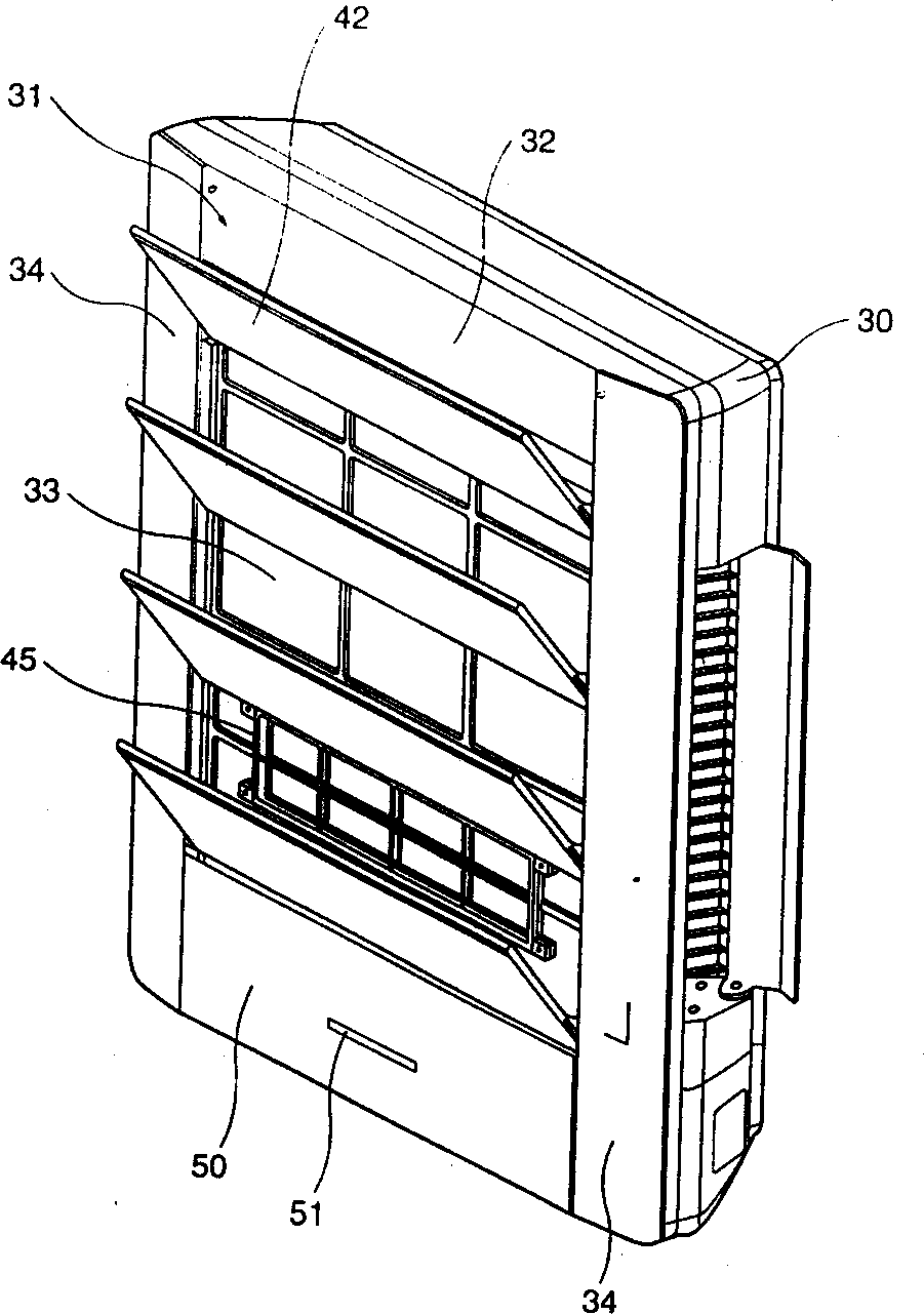
[0032] Such as image 3 As shown, the shell 30 forms the shape of the indoor unit of the air conditioner. The basic shape of the shell 30 is a flat hexahedron. The front of the shell 30 is provided with a front plate 31, so that the inside of the shell forms a closed space.

[0033] The detailed structure of front plate 31 is as Figure 4 As shown, the shape of the front plate body 32 is approximately rectangular, and there is a quadrilateral air inlet 33 in the center thereof, and the air inlet 33 sucks air into the air conditioner, and the filter 45 to be described below is distributed in the air inlet 33 The air inlet frame 33', the air inlet frame 33' adopts a grid structure.

[0034] The two ends of front plate body 32 are respectively provided with the longer decorative plate 34 from top to...


PUM


Abstract

A lifting unit for the baseplate of air conditioner is composed of front plate on the casing of air conditioner, the baseplate at lower end of front plate, the baseplate-lifting transmission mechanism with gear-rack structure, and the baseplate-lifting driver. The said baseplate is in contact with two side ends of said front plate and at the contact position there are relative slot and hump structure. Its advantage is easy replacing air filter.

Description

technical field [0001] The invention relates to an air conditioning device, in particular to a floor lifting device used in an air conditioner. Background technique [0002] figure 1 The structure of the indoor unit of the prior art split air conditioner is shown. [0003] Such as figure 1 As shown, the shell 1 forms the shape of the indoor unit of the air conditioner, and its outline shape is a thin cuboid, that is, its upper, lower, left and right dimensions are larger than the front and rear dimensions. A front panel 2 is arranged on the front of the casing 1, and an air inlet 2' is recessed in the front panel 2 so as to suck air into the air conditioner. In order to purify the air passing through the air inlet 2', a There is a filter 4, and an air inlet grille 5 is arranged in front of the air inlet 2'. Due to the blocking of this air inlet grille 5, although the inside of front panel 2 cannot be seen from the outside, air can still be...

Claims


Application Information

Patent Timeline
03 Jul 2002
Publication
CN1356514A
IPC
F24F13/20; F24F13/28
Inventors
池宗佑