Motor with electrically slipping rotor spindle and purpose

A technology of rotor shaft and motor, applied in the field of transmission system, can solve the problems of enlarged transmission system space, increased operation and maintenance workload, complicated control, etc., and achieves the effect of simplifying installation work, reducing maintenance workload and fast response speed

Inactive Publication Date: 2010-06-30
WUHAN UNIV OF TECH +1
View PDF0 Cites 4 Cited by
  • Summary
  • Abstract
  • Description
  • Claims
  • Application Information

AI Technical Summary

Problems solved by technology

The former needs to increase the hydraulic transmission control system, and the latter needs to increase the gear device. Both of them increase the space of the transmission system, complicate the control, and increase the workload of operation and maintenance.

Method used


Image

  • Motor with electrically slipping rotor spindle and purpose
  • Motor with electrically slipping rotor spindle and purpose
  • Motor with electrically slipping rotor spindle and purpose

Examples


Embodiment Construction

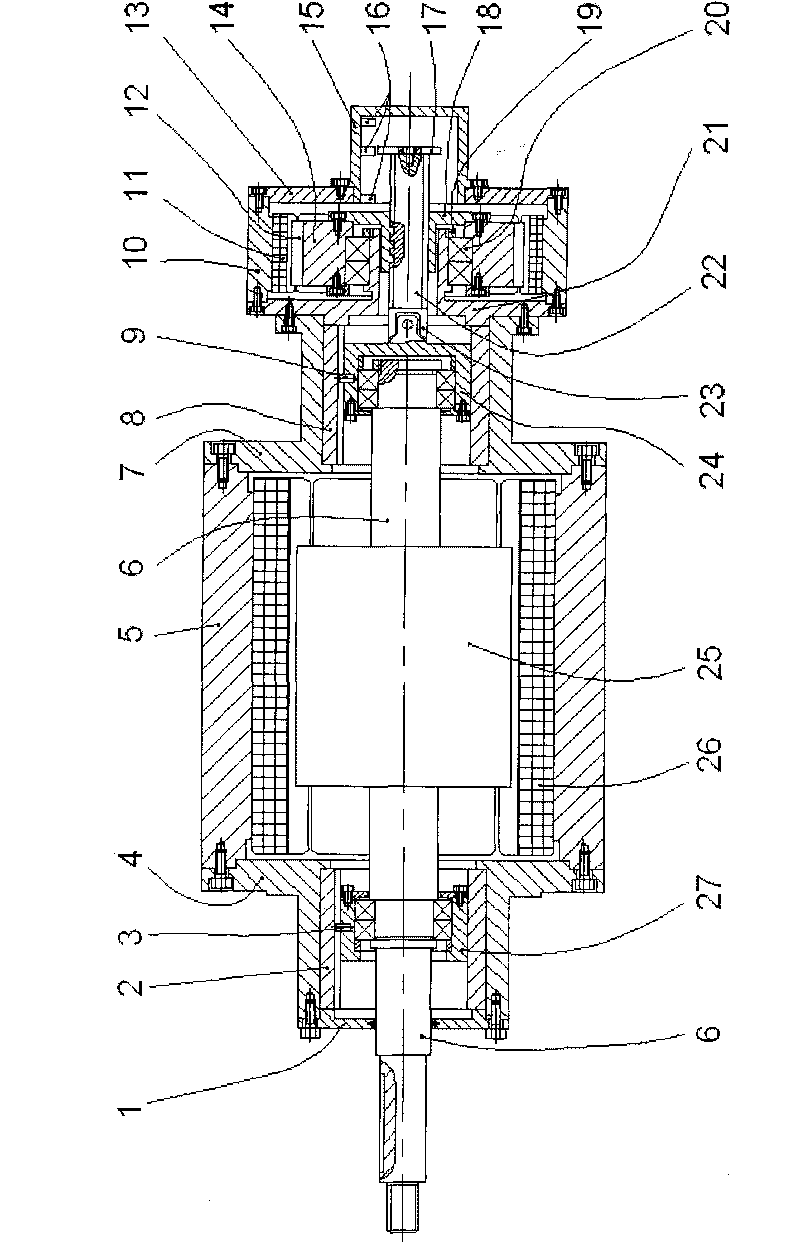
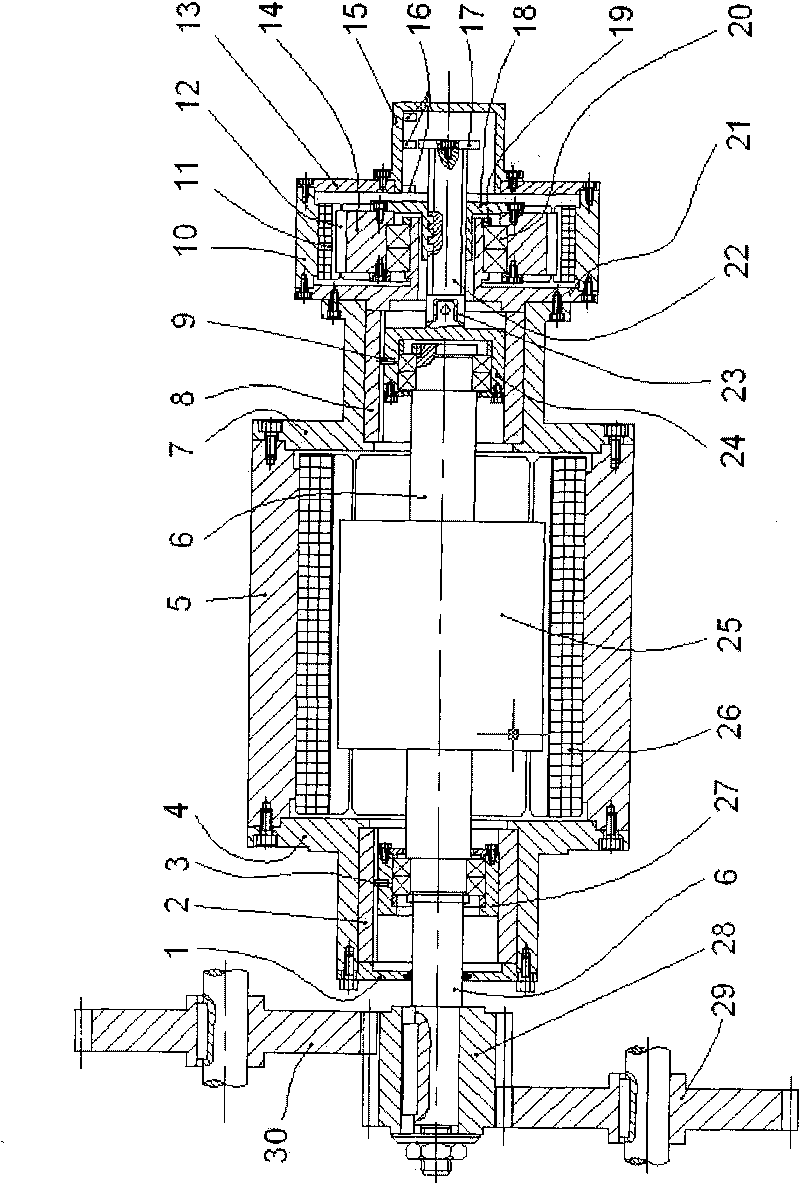
[0017] The motor for electric sliding of the rotor shaft provided by the invention comprises a set of motor stator and motor rotor, and a set of sliding driving mechanism. One end of the rotor shaft of the motor rotor is installed with a drive gear to output torque, and the other end is installed with a slip drive mechanism. The sliding drive mechanism is mainly composed of a screw rod and a nut, an auxiliary stator and an auxiliary rotor, wherein the nut is coaxially installed on the auxiliary rotor. When the auxiliary rotor drives the nut to rotate, the screw rod matched with the nut will move axially and linearly, and finally the motor rotor shaft will slip axially. The axial slip position of the rotor shaft is detected by multiple position sensors installed at the end of the motor, and the rotor shaft of the motor can slip to a certain position through the control of the slip drive mechanism.

[0018] The motor is suitable for multi-transmission chain mechanical equipment...


PUM


Abstract

The invention relates to a motor with an electrically slipping rotor spindle, which is composed of a rotor (25), a stator and a slip drive mechanism, wherein one end of a rotor spindle (6) of the rotor is provided with a drive gear (28) for outputting torque, and the other end is provided with the slip drive mechanism mainly composed of a screw rod (22), screws (18), an auxiliary rotor (14) and an auxiliary stator; and the screws (18) are axially arranged on the auxiliary rotor (14) and connected with the screw rod (22) through threads. When the auxiliary rotor (14) drives the screws (18) to rotate, the screw rod (22) matched with the screws is caused to linearly move axially so that the rotor spindle (6) produces axially slip of which the position is detected by a plurality of position sensors (16) arranged on the end of the motor. The motor has compact structure and can simplify the structure of a machinery drive system when being used in change drive or multi-position drive machinery.

Description

technical field [0001] The invention relates to a motor for electric sliding of a rotor shaft. The electric motor is used in electric-driven multi-transmission chain mechanical equipment, and is especially suitable for the transmission system of rapier looms. Background technique [0002] Transmission devices driven by electric motors are widely used in mechanical equipment. The rotor shaft of a general motor is fixed relative to the stator in the axial direction. When the mechanical device needs to be driven by a time-sharing multi-transmission link, the intermediate gear is usually used to change the transmission route, and a corresponding fork operating mechanism is provided. The other The method is to set the clutch to split the transmission link. The mechanical structure of these variable transmission chain drives is complex. In some applications, the driving gear on the rotor shaft of the motor can be directly moved to change the transmission chain. For example, in ...

Claims


Application Information

Patent Timeline
Patent Type & Authority Applications(China)
IPC IPC(8): H02K7/116H02K11/00D03D51/00H02K11/21
Inventor 夏泽中贺力袁佑新刘军陈静方长全
Owner WUHAN UNIV OF TECH
Why Eureka
Try Eureka