Vacuum disconnector

A circuit breaker and vacuum technology, applied in the direction of high-voltage air circuit breakers, circuits, electrical switches, etc., can solve the problems of limited space, difficult maintenance and repair of vacuum circuit breakers, complicated mechanisms, etc.

Inactive Publication Date: 2002-07-10
LG IND SYST CO LTD
View PDF0 Cites 15 Cited by
  • Summary
  • Abstract
  • Description
  • Claims
  • Application Information

AI Technical Summary

Problems solved by technology

Therefore, if the vacuum breaker is installed in the rear interior of the power distribution terminal box (not shown), the installation space here is complicated and limited, it is difficult to ensure the installation space in the power distribution terminal box, and due to the Space is limited and vacuum breakers are difficult to maintain and service
[0018] Also, according to the vacuum breaker in the prior art, the power transmission mechanism, such as the transmission rod 38 for t

Method used


Image

  • Vacuum disconnector
  • Vacuum disconnector
  • Vacuum disconnector

Examples


Embodiment Construction

[0032] Hereinafter, reference will be made in detail to a preferred embodiment of the present invention, which is shown in the accompanying drawings.

[0033] According to the present invention, there can be many embodiments of the vacuum interrupter. Here, the most preferred embodiment will be described.

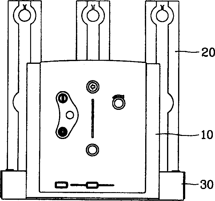
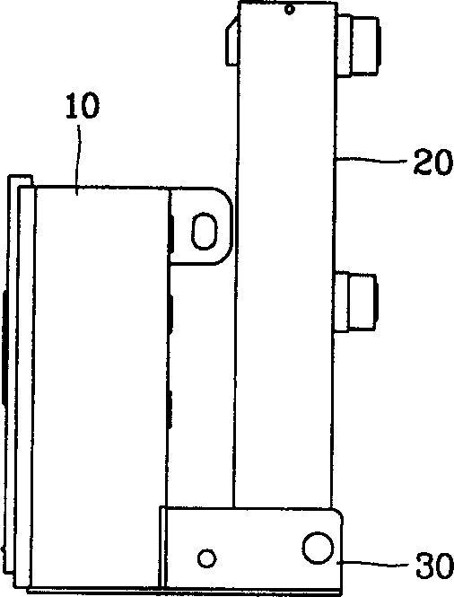
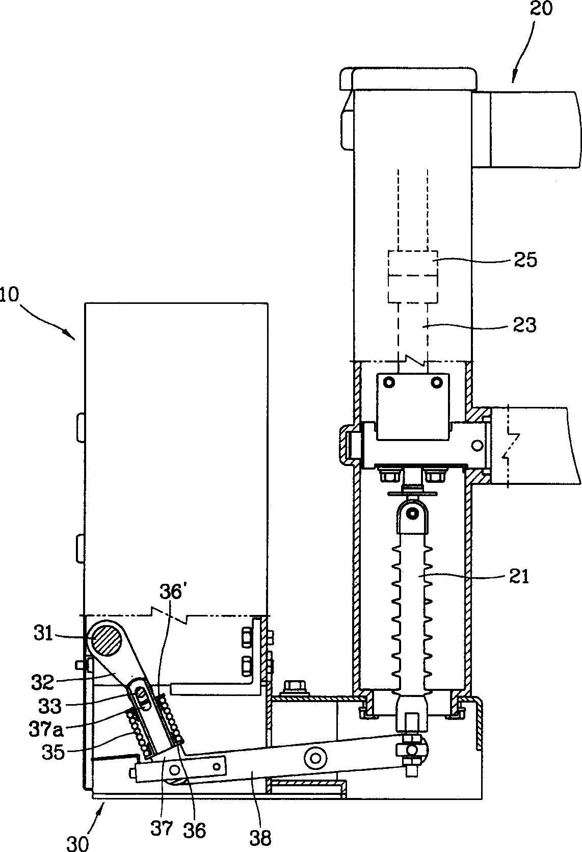
[0034] Attached Figure 4 It is a perspective view of the vacuum circuit breaker of the present invention.

[0035]As shown in the figure, the vacuum circuit breaker of the present invention includes three switch mechanism units 60A, 60B, and 60C, which are arranged along the length direction, and respectively include a movable circuit for connecting or disconnecting the power supply and the electric load. Contact 63 and fixed contact 65; an actuator unit 50, at least one rotating shaft that provides dynamic power to move the movable contact 63 to a position where it contacts or separates from the fixed contact 65; a bracket 66, It is used to fix and support the switch mechanis...


PUM


Abstract

A vacuum circuit breaker comprises: a plurality of switching mechanism units having movable contacts and stationary contacts for connecting/breaking an electric circuit between an electric source and an electric load respectively, and disposed in lengthwise direction; an actuator unit including at least one rotary shaft for providing the movable contacts with dynamic power so as to move to positions contacting to the stationary contacts or to positions separating from the stationary contacts; a supporting frame for fixing and supporting the switching mechanism units and the actuator unit; and a transfer link unit for transferring rotating movement of the rotary shaft to a plurality of vertical movements, whereby the vacuum circuit breaker can be easily installed in a power distributing cabinet and a power of the actuator unit can be evenly transmitted to the plurality of switching mechanism units.

Description

Technical field [0001] The present invention relates to a vacuum circuit breaker, that is, an industrial electronic equipment used between power transmission and distribution devices of industrial cables, and more particularly to a vacuum circuit breaker, which can pass through a switch mechanism unit and a switch mechanism unit in the length direction. The actuator unit is installed in a narrow power distribution terminal box. At the same time, the power of the actuator unit can be evenly transmitted to multiple switchgear units. Background technique [0002] Generally, a circuit breaker is an electronic protection device, which can protect electric load devices and power cables from being damaged by large fault currents due to insufficient power and grounding errors in the circuit, and when such fault currents are generated The power-off operation is automatically performed, thereby disconnecting the circuit. [0003] A vacuum circuit breaker is a type of ci...

Claims


Application Information

Patent Timeline
IPC IPC(8): H02B1/32H01H33/02H01H33/42H01H33/66H01H33/666
CPCH01H33/666H01H33/022H01H33/66
Inventor 尹石重
Owner LG IND SYST CO LTD
Why Eureka
Try Eureka