
High-efficient engine

An engine and high-efficiency technology, applied in variable displacement engines, machine/engines, reciprocating piston engines, etc., can solve problems such as unreasonable engine transmission structures, reduce fuel consumption, reduce construction costs, and reduce engine weight Effect

Inactive Publication Date: 2002-08-07
訾应举
View PDF0 Cites 12 Cited by
  • Summary
  • Abstract
  • Description
  • Claims
  • Application Information

AI Technical Summary

Problems solved by technology

This is a serious loss caused by unreasonable engine transmission structure (connecting rod and crankshaft)

Method used


Image

  • High-efficient engine
  • High-efficient engine
  • High-efficient engine

Examples


Embodiment Construction

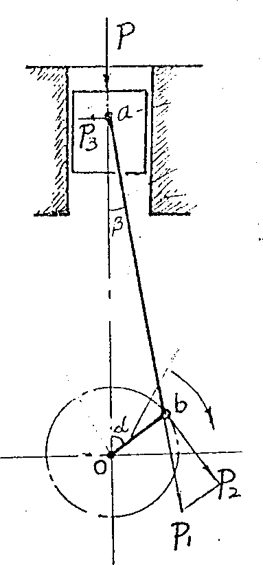
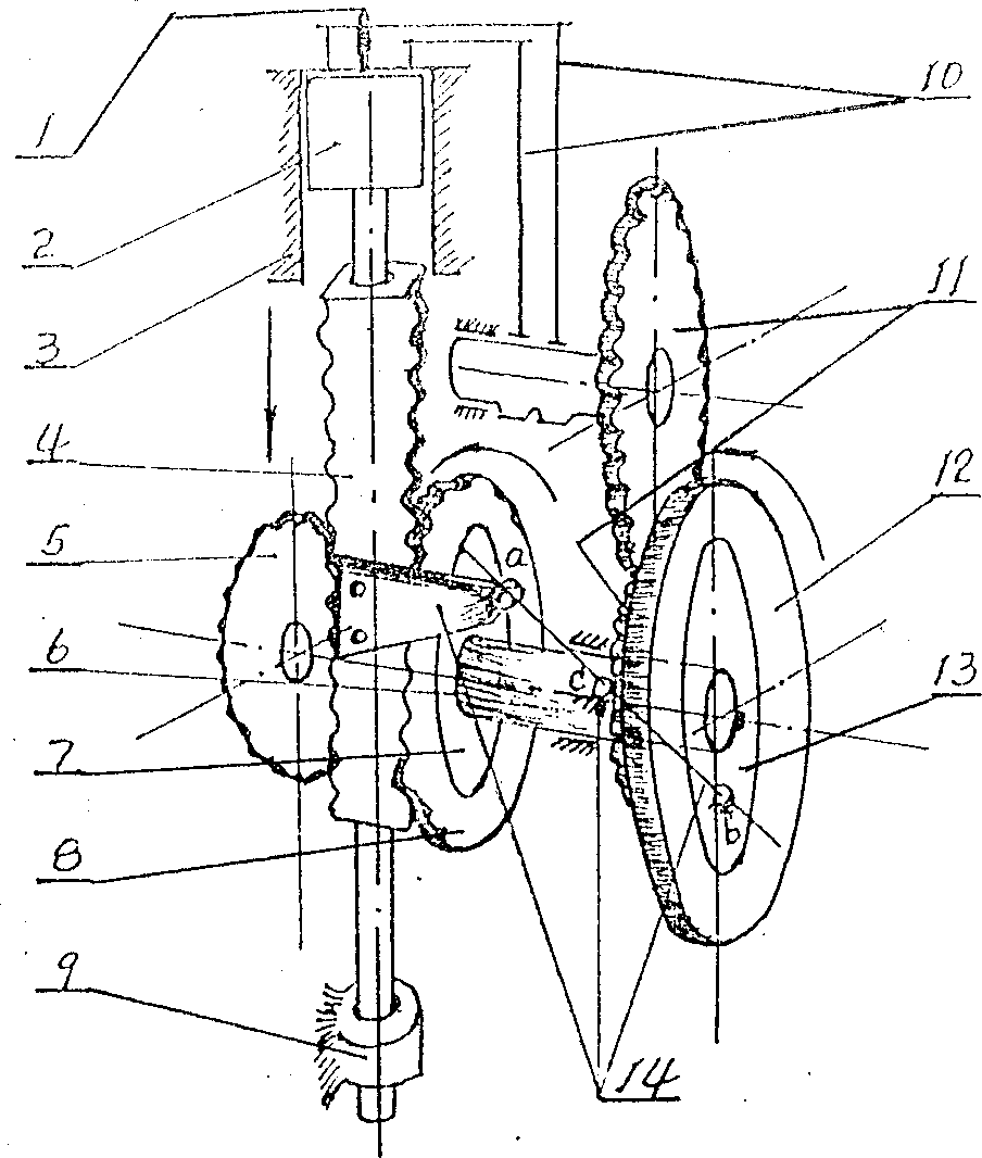
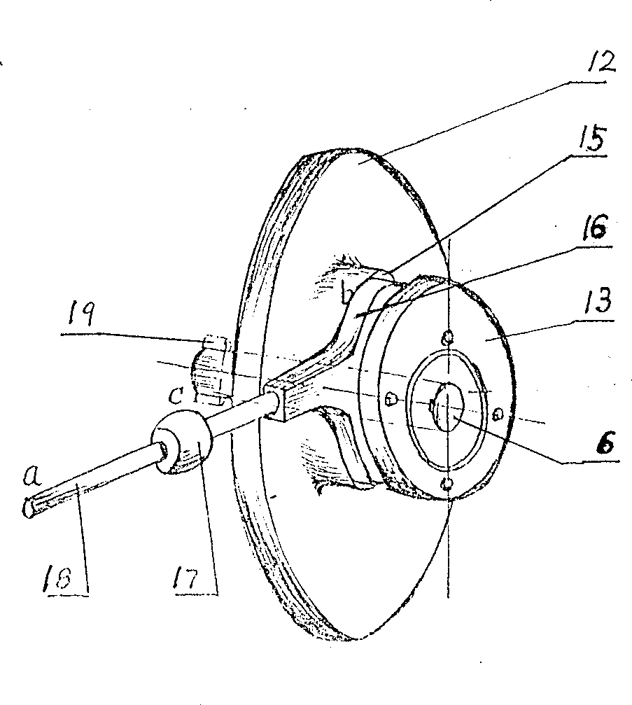
[0017] The structures disclosed in the above drawings are embodiments of the present invention. In the figure, 1 is the fuel injector; 2 is the piston; 3 is the cylinder block; 4 is the piston rod with rack; 5 is the transmission gear; 6 is the main shaft; Main shaft gear; 9 is the bearing located at the bottom of the piston rod; 10 is the intake and exhaust mechanism; 11 is the timing gear; 12 is the flywheel; 13 is the overrunning clutch; 14 is the lever transmission mechanism (including lever ab and its hinges a, b, c and the connecting block located on the rack); 15 is a circular eccentric groove located at the middle part of the flywheel 12; 16 is a circular eccentric ring located in the eccentric groove; 17 is a supporting hinge (ie C); 18 is a lever (i.e. ab); 19 is the braking device that prevents the main shaft from idling; 20 is the outer ring of the clutch; 21 is the inner ring of the clutch. The specific situation of the above-mentioned overrunning clutch can be f...


PUM


Abstract

The high-efficiency motor is characterized by that under the piston of cylinder a piston rod with rack is set, and said rack and the components of main shaft gear, clutch, flywheel and lever are formed into a driving mechanism. Said driving mechanism can centralize the fuel explosion pressure in the cylinder, and make it downward act on the piston rod to make it upward and downward reciprocate toraise its power and efficiency, and reduce fuel consumption.

Description

technical field [0001] The invention relates to an engine, especially an engine with high efficiency and low fuel consumption. Background technique [0002] The working principle of the engines (gasoline engines and diesel engines) used in existing automobiles, tractors, ships, etc. is as follows: figure 1 : The explosion pressure P of the fuel in the cylinder pushes the piston transmission connecting rod to move down, and the connecting rod pushes the crank to make the main shaft rotate to do work. P is decomposed into P1 and P3, and P3 is absorbed by the cylinder wall, which is a useless loss. P1 that pushes the connecting rod to move and P2 that acts on the crank to rotate the main shaft are as follows: [0003] P1=P×cosβ [0004] P2=P1×sin(α+β)=P×cosβ×sin(α+β) [0005] That is, only part (P2) of the explosion pressure P in the cylinder is utilized to do work, and the rest is completely consumed uselessly. The size of P2 varies with the crank ang...

Claims


Application Information

Patent Timeline
IPC IPC(8): F01B9/04
CPCF01B9/047
Inventor 訾应举
Owner 訾应举
Features
  • Generate Ideas
  • Intellectual Property
  • Life Sciences
  • Materials
  • Tech Scout
  • Unparalleled Data Quality
  • Higher Quality Content
  • 60% Fewer Hallucinations
Learn More