Electric device and apparatus for charging battery unit, and method for charging and discharging

A battery unit and electric device technology, applied in secondary battery charging/discharging, electric vehicle charging technology, electrical devices, etc., can solve control difficulties, difficulties in accurate management of residual capacity of battery packs, and control of inability to discharge and charge And other issues

Inactive Publication Date: 2002-09-11
TOKYO R & D LTD
View PDF1 Cites 26 Cited by
  • Summary
  • Abstract
  • Description
  • Claims
  • Application Information

AI Technical Summary

Problems solved by technology

[0030] However, when a large load is applied when the vehicle starts, accelerates, etc., and a large current discharge is required, a plurality of battery packs connected in parallel are discharged separately. The group is discharged with a small current, so it is difficult to accurately manage the remaining capacity of each battery group, and it is impossible to control the most efficient discharge and charge.
[0031] In particular, in the case of using a storage battery pack that is repeatedly charged and discharged in a state where the depth of discharge is shallow, a so-called memory effect occurs in which the capacity of the battery is reduced. Although it is best to carry out individual battery packs in order to prevent this memory effect, Optimal charge and discharge control, but this control is difficult
[0032] In addition, when the battery pack that has been discharged to the specified remaining capacity is taken out from the vehicle and charged by a charging device at another place, the management of the batteries will be managed in a uniform order, so it is impossible to confirm the status of the battery pack when it is taken out. Charge and discharge conditions, the best charge control

Method used


Image

  • Electric device and apparatus for charging battery unit, and method for charging and discharging
  • Electric device and apparatus for charging battery unit, and method for charging and discharging
  • Electric device and apparatus for charging battery unit, and method for charging and discharging

Examples


no. 1 Embodiment

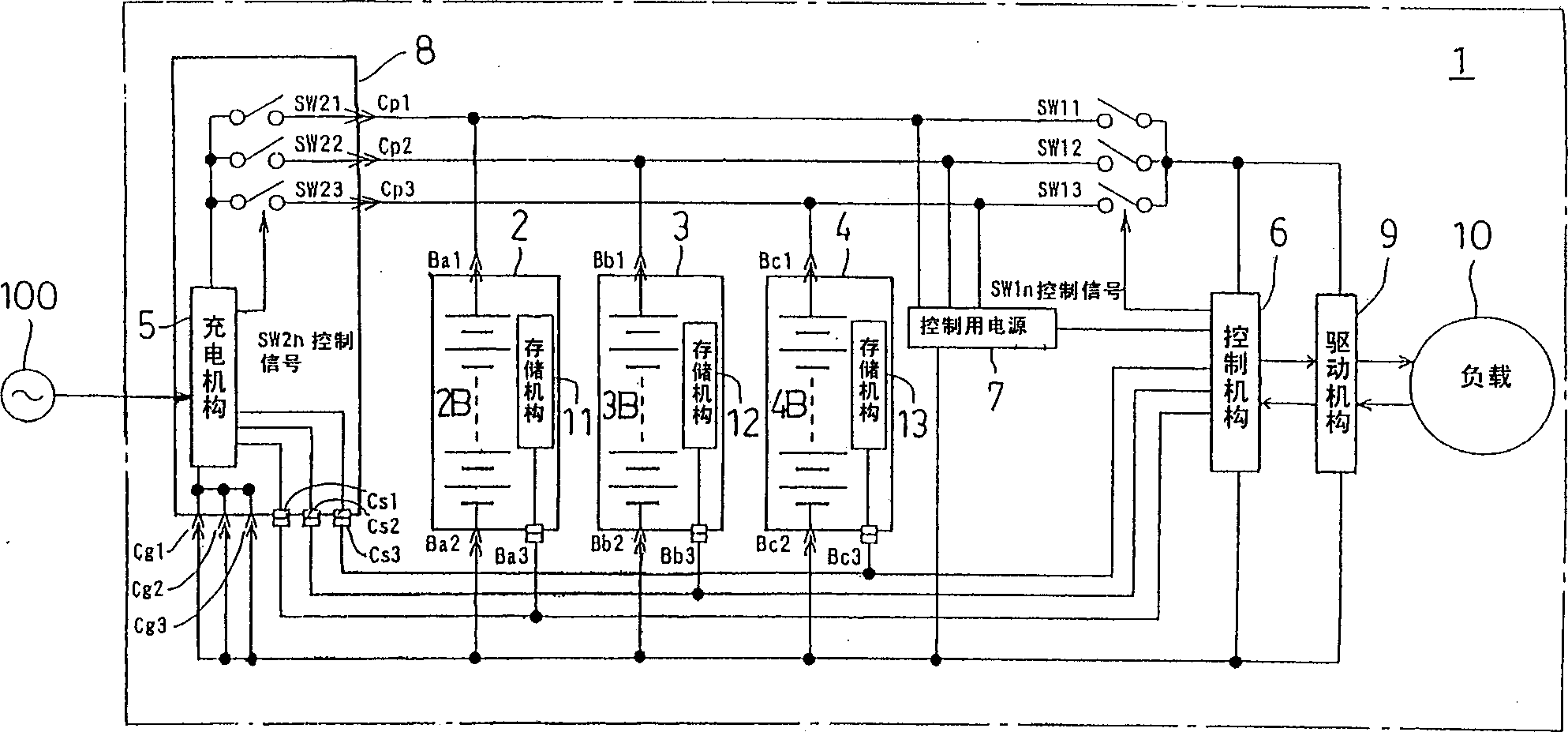
[0095] figure 1 FIG. 1 is a block circuit diagram showing an electric device equipped with a battery unit according to a first embodiment of the present invention.

[0096] The electric device 1 of this embodiment is equipped with a plurality of battery cells 2, 3, 4 in a detachable manner on the device main body (not shown), and a charging unit 8 for charging the battery packs 2B, 3B, 4B. .

[0097] The battery units 2 , 3 , 4 have the same configuration, and are units in which the battery packs 2B, 3B, 4B and storage mechanisms 11 , 12 , 13 such as EEPROM are integrated in pairs, respectively. On each battery unit 2, 3, 4 and the battery unit loading portion (not shown) of the device main body, as the battery units 2, 3, 4 are attached and detached, the electrical connection and separation from the device main body side are respectively performed. The connecting mechanism is provided with connectors Ba1, Ba2, Ba3, connectors Bb1, Bb2, Bb3, and connectors Bc1, Bc2, Bc3 whi...

no. 2 Embodiment

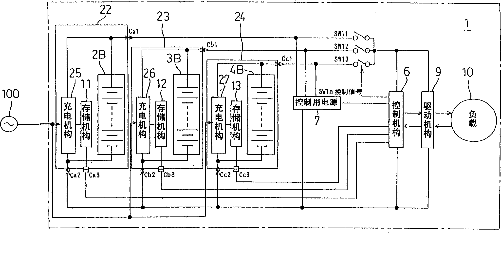
[0161] figure 2 is a block circuit diagram showing an electric device equipped with a battery unit according to a second embodiment of the present invention, for the figure 1 The same parts are given the same reference numerals to omit or simplify their descriptions.

[0162] The battery units 22, 23, 24 of the second embodiment are the same as the battery units of the first embodiment, respectively, and the storage units 11, 12, 13 for storing the information of the charging and discharging status of the battery packs 2B, 3B, 4B Integrate in pairs, and respectively built-in with figure 1 The charging mechanism 5 identical charging mechanism 25,26,27 that is located on the charging unit 8. Therefore, the battery units 22, 23, and 24 in this case can also be called power supply units.

[0163] Furthermore, each battery unit 22 , 23 , 24 is mounted on the main body of the electric device 1 in a detachable manner. On each of the battery units 22, 23, 24 and the battery uni...

no. 3 Embodiment

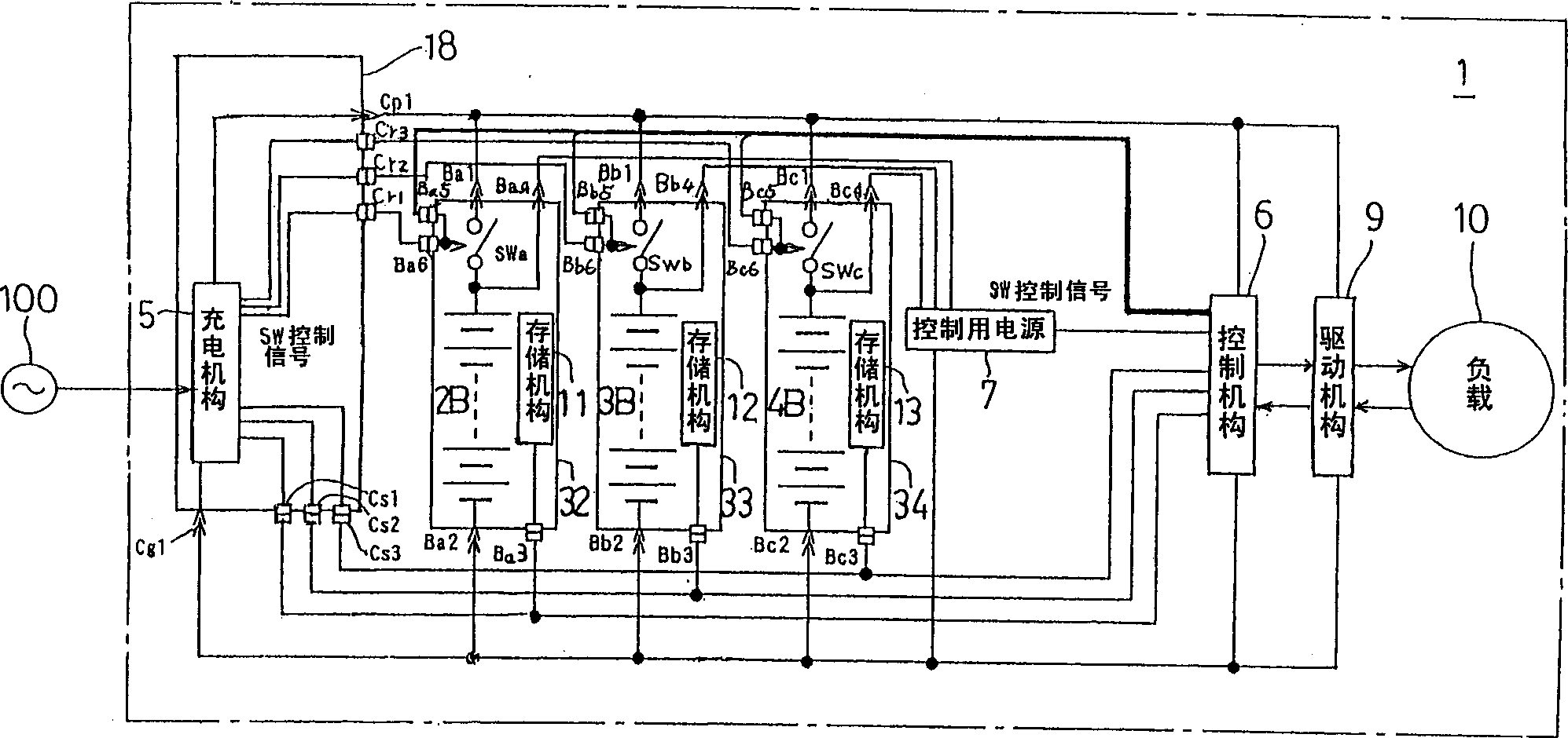
[0211] image 3 is a block circuit diagram showing an electric device equipped with a battery unit according to a third embodiment of the present invention, and figure 1 The same reference numerals are given to the same parts, and the description thereof will be omitted.

[0212] Should image 3 The battery units 32, 33, and 34 of the third embodiment shown in Fig. , 13 are integrated in pairs, and switches SWa, SWb, SWc are provided in series with the battery packs 2B, 3B, 4B, respectively.

[0213] These switches allow both figure 1 The functions of the switches SW21, SW22, SW23 in the charging unit 8 and the switches SW11, SW12, SW13 controlled by the control mechanism 6 can reduce the cost of the product.

[0214] Furthermore, these battery cells 32 , 33 , and 34 are detachably mounted on the main body of the electric device 1 . Each of the battery units 32, 33, 34 is respectively provided with a series circuit of the battery pack 2B, 3B, 4B and the switches SWa, SW...


PUM


Abstract

An electric device, comprising a plurality of detachable battery units 2, 3, 4, each comprising a battery pack 2B, 3B, 4B and a storage mechanism 11, 12, 13 for storing information about the charging and discharging status of the battery. A connection mechanism is provided to electrically connect and disconnect the electric device 1 in response to each battery cell being attached and detached. The device includes a driving mechanism 9 for driving a load, a charging mechanism 5 for charging the accumulators 2B, 3B, 4B with reference to information stored in the storage mechanisms 11, 12, 13 of the installed battery units 2, 3, 4, and The control means 6 controls the electric power supplied from each battery unit 2, 3, 4 to the drive means 9 with reference to the above-mentioned information.

Description

technical field [0001] The present invention relates to an electric device such as an electric vehicle such as an electric two-wheeled vehicle or an electric wheelchair using electric energy of a battery as a power source, a charging device for charging the battery unit thereof, and a method for charging and discharging the battery unit. Background technique [0002] Like an electric two-wheeled vehicle or an electric wheelchair, there is an electric vehicle equipped with a storage battery pack composed of a plurality of storage batteries as a power source. Among such electric vehicles, there are vehicles that drive the electric motor with electric energy (electric power) from a mounted battery pack and run only by the driving force, or vehicles that run by the combined force of the driving force of the electric motor and human power, or A vehicle, etc. that switches between the driving force of the gasoline engine and the driving force of the electric motor. [0003] The s...

Claims


Application Information

Patent Timeline
Patent Type & Authority Applications(China)
IPC IPC(8): H02J7/02B60L11/18H01M10/44H02J7/00H02J9/06
CPCH02J7/0024H02J9/06Y02T90/14Y02T10/7072B60L3/12B60L2210/30B60L2240/12B60L2240/545B60L2240/547B60L2240/549B60L2240/80B60L2250/10B60L2250/16Y04S30/14B60L53/14B60L50/51B60L53/65B60L58/21B60L58/15H01M10/4257B60L58/10Y02T10/70Y02T10/72Y02T90/12Y02T90/167Y02E60/10H02J7/00B60L3/0046Y02T90/16
Inventor 石井广青木隆大沼伸人
Owner TOKYO R & D LTD
Why Eureka
Try Eureka