Secondary battery state detecting system, secondary battery state detecting device, and secondary battery state detecting method

A state detection device, secondary battery technology, applied in battery circuit devices, battery/fuel cell control devices, electrical devices, etc.

Pending Publication Date: 2020-08-04
HONDA MOTOR CO LTD
View PDF11 Cites 0 Cited by
  • Summary
  • Abstract
  • Description
  • Claims
  • Application Information

AI Technical Summary

Problems solved by technology

[0005] However, in the technology described in Patent Document 2, the information on the secondary battery at the past time when the secondary battery is used in other equipment is not used to control the charging current to the secondary battery.
In addition, in the technique described in Patent Document 2, the charging current to the secondary battery is not controlled by using information on a secondary battery other than the secondary battery.

Method used


Image

  • Secondary battery state detecting system, secondary battery state detecting device, and secondary battery state detecting method
  • Secondary battery state detecting system, secondary battery state detecting device, and secondary battery state detecting method
  • Secondary battery state detecting system, secondary battery state detecting device, and secondary battery state detecting method

Examples


no. 1 approach

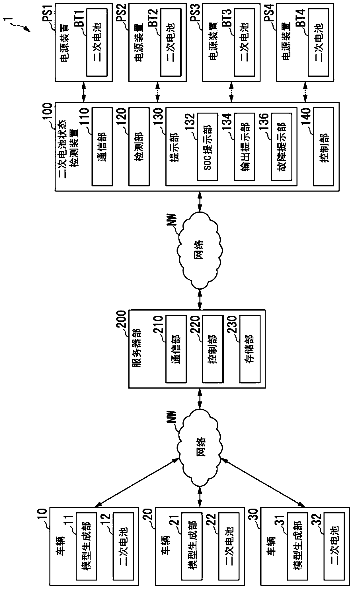
[0032] figure 1 It is a figure which shows the 1st example of the secondary battery state detection system 1 of 1st Embodiment.

[0033] exist figure 1 In the illustrated example, the secondary battery state detection system 1 includes, for example, three vehicles 10 , 20 , and 30 , a server unit 200 , a secondary battery state detection device 100 , and a power supply device PS1 .

[0034] In another example, the secondary battery state detection system 1 may include any number of vehicles other than three.

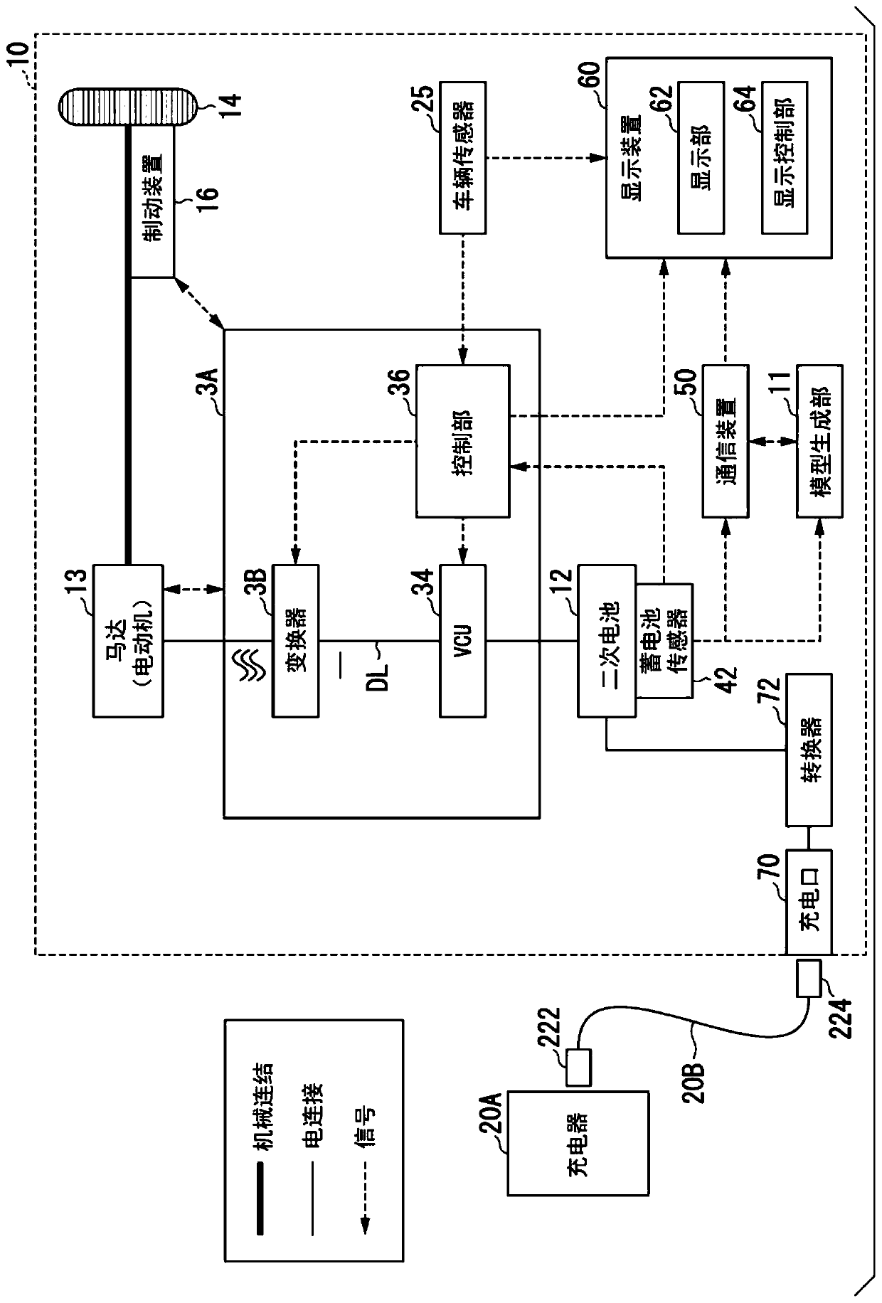
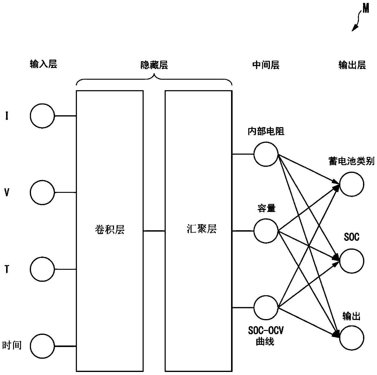
[0035] exist figure 1 In the illustrated example, a vehicle 10 includes a model generation unit 11 and a secondary battery 12 . That is, secondary battery 12 is mounted on vehicle 10 . The model generator 11 generates a secondary battery model M that models the characteristics of the secondary battery 12 (see image 3 ). Specifically, the model generation unit 11 is based on the battery sensor 42 (refer to figure 2 ) to generate the secondary battery model M by d...

no. 2 approach

[0119] Hereinafter, a second embodiment of the secondary battery state detection system, secondary battery state detection device, and secondary battery state detection method of the present invention will be described. The secondary battery state detection system 1 of the second embodiment has the same configuration as the secondary battery state detection system 1 of the above-mentioned first embodiment except for the points described later. Therefore, according to the secondary battery state detection system 1 of the second embodiment, the same effects as those of the secondary battery state detection system 1 of the above-mentioned first embodiment can be obtained except for the points described later.

[0120] Figure 5 It is a figure which shows the 1st example of the secondary battery state detection system 1 of 2nd Embodiment.

[0121] exist figure 1 In the example shown, the vehicle 10 is equipped with the model generation unit 11, the vehicle 20 is equipped with th...


PUM


Abstract

The invention provides a secondary battery state detecting system, a secondary battery state detecting device, and a secondary battery state detecting method. A secondary battery state detecting system includes: a model generating unit that generates a plurality of secondary battery models acquired by modeling characteristics of a plurality of secondary batteries mounted in a plurality of vehicles; a server unit that collects the plurality of secondary battery models generated by the model generating unit and provides the collected secondary battery models as secondary use secondary battery control information used for charging / discharging control of a secondary battery that is secondarily used; and a secondary battery state detecting device that executes charging / discharging control of the secondary battery that is secondarily used by using the secondary use secondary battery control information provided from the server unit.

Description

technical field [0001] The invention relates to a secondary battery state detection system, a secondary battery state detection device and a secondary battery state detection method. Background technique [0002] Japanese Patent No. 6207127 (hereinafter referred to as Patent Document 1) describes a measurement system including a storage battery pack incorporating a storage battery, and at least one connection device connected to the storage battery pack. In the technique described in Patent Document 1, the discharge current from the battery is detected in a first measurement range, and the charging current to the battery is detected in a second measurement range smaller than the first measurement range to calculate the charging capacity of the battery. [0003] However, in the technique described in Patent Document 1, the capacity of the storage battery is not calculated using information on the storage battery at a past time when the storage battery is used in another devic...

Claims


Application Information

Patent Timeline
IPC IPC(8): G01R31/385G01R31/389G01R31/378G01R31/367B60L58/10
CPCG01R31/385G01R31/389G01R31/378G01R31/367B60L58/10Y02T10/70H02J7/0048H02J7/007194H02J7/00041H02J7/00714H02J7/007182H02J2310/48B60L53/31B60L2240/549B60L2240/547B60L2240/545B60L58/16B60L3/12B60L3/0046Y04S30/12G06N20/00G06N5/046Y02T10/7072Y02T90/12Y02T90/167H02J7/00712G06N5/04B60L58/12
Inventor 西田义一
Owner HONDA MOTOR CO LTD
Why Eureka
Try Eureka