Moulding die, mould system, recording medium base plate, recording medium, optical disc base plate, optical disc, moulding die making method

A technology for recording media and substrates, which is applied in the manufacture of optical record carriers, optical record carriers, thin material processing, etc., and can solve problems such as high manufacturing costs, obstruction of mold expansion and contraction, and increased dynamic imbalance

Inactive Publication Date: 2002-11-13
TDK CORPARATION
View PDF6 Cites 3 Cited by
  • Summary
  • Abstract
  • Description
  • Claims
  • Application Information

AI Technical Summary

Problems solved by technology

However, the problem with the method of bonding the transparent sheet to the substrate is that the manufacturing cost is high due to strict requirements on the optical characteristics or thickness accuracy of the light-transmitting layer.
Therefore, for example, as disclosed in Japanese Laid-Open Patent Publication No. Hei 5-200791, it is necessary to remove the above-mentioned protrusions through post-processing, and the manufacturing cost increases.
[0012] (2) The problem of substrate burrs
[0016] (3) The problem of mold deterioration
However, if this is the case, the end edge 110A of the inner peripheral wall 110 of the annular mold 102 will be damaged, and the annular mold 102 must be frequently replaced.
In addition, the expansion and contraction of the stamper due to the heat of the molten resin is hindered, and good molding is difficult.
[0018] (4) The problem of uneven thickness of the transparent layer
[0023] However, in the case of this method, if the processing accuracy when removing the outer periphery of the substrate is deteriorated, since the concentricity between the outer diameter (outer peripheral side) and the inner diameter of the substrate decreases, the dynamic imbalance when it is mounted on the optical disc drive and rotates increase, causing trouble for recording / playback
In addition, since the outer peripheral part is removed, the utilization rate of the material is poor

Method used


Image

  • Moulding die, mould system, recording medium base plate, recording medium, optical disc base plate, optical disc, moulding die making method
  • Moulding die, mould system, recording medium base plate, recording medium, optical disc base plate, optical disc, moulding die making method
  • Moulding die, mould system, recording medium base plate, recording medium, optical disc base plate, optical disc, moulding die making method

Examples


Embodiment Construction

[0073] Embodiments of the present invention will be specifically described below with reference to the accompanying drawings.

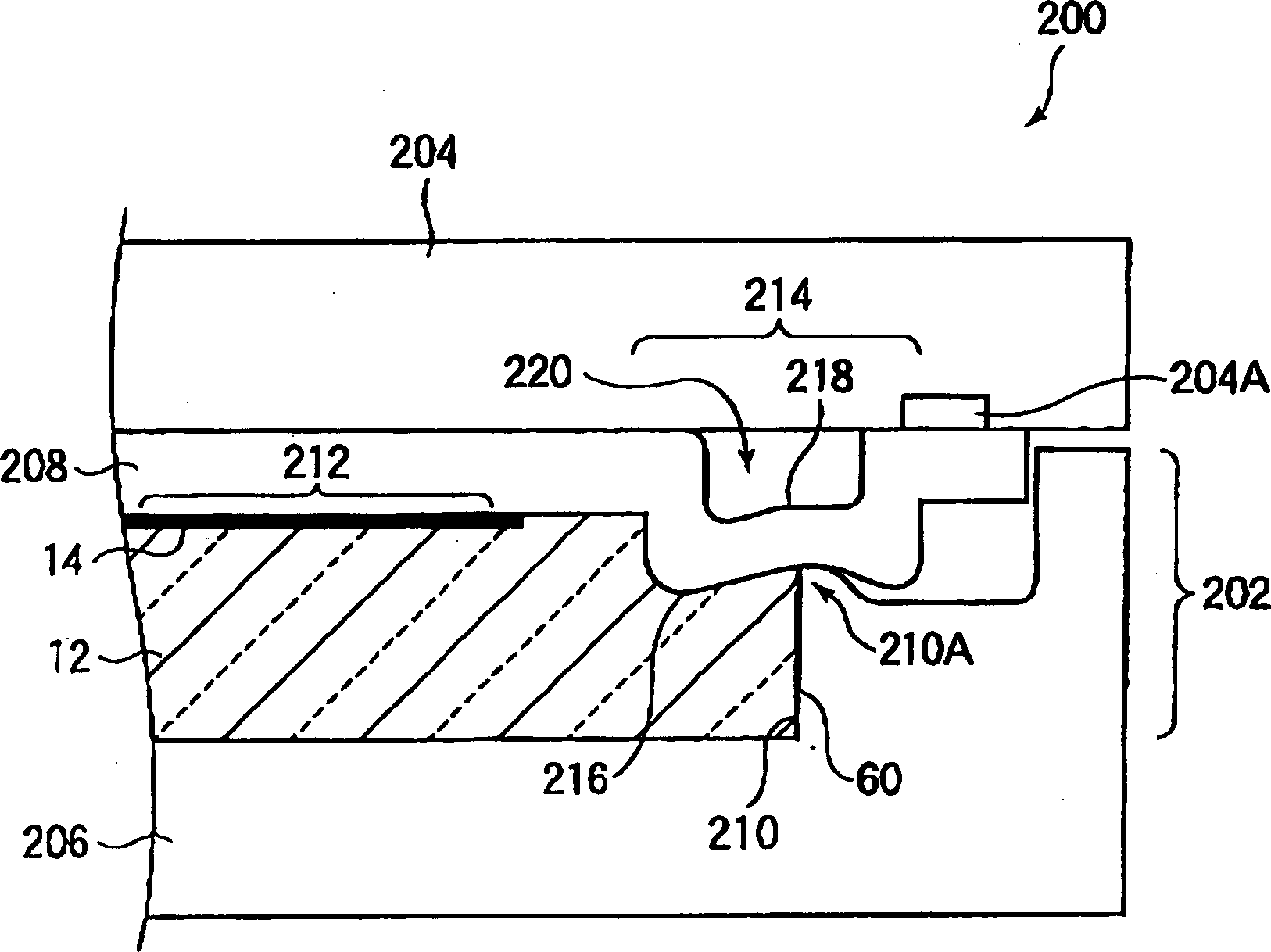
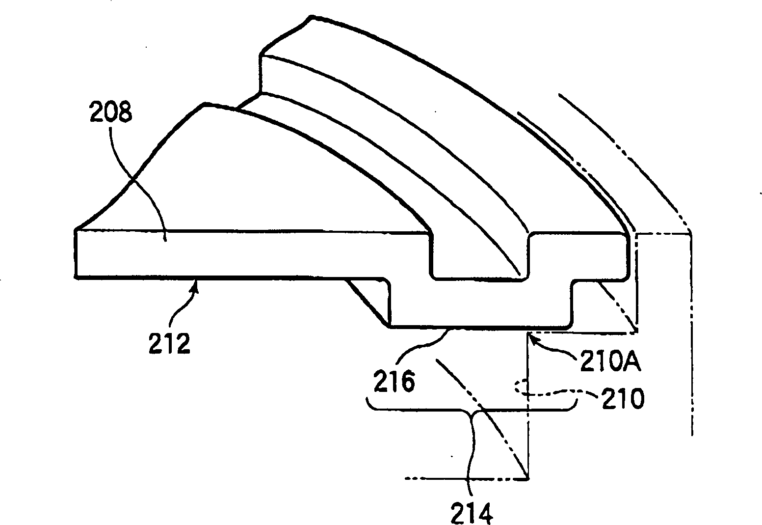
[0074] figure 1 The mold system 200 of this embodiment is shown in . The mold system 200 includes an annular mold 202 , planar molds 204 , 206 arranged face to face, and a die 208 disposed on one side ( 204 ) of the planar dies 204 , 206 . Here, the flat die 206 is provided integrally with the annular die 202 . The ring mold 202 includes an inner peripheral wall 210 that can form the outer peripheral surface 60 of the substrate 12 for the recording medium. In addition, the front surface and the back surface of the substrate 12 are formed by the above-mentioned pair of planar molds 204,206. The stamper 208 has a reprint surface 212 on which minute unevenness for reprinting predetermined information is formed, so that the information recording surface (area) 14 is formed on the substrate 12 . In addition, the above-mentioned information recording s...


PUM

PropertyMeasurementUnit
wavelengthaaaaaaaaaa
thicknessaaaaaaaaaa
wavelengthaaaaaaaaaa

Abstract

The object of the present invention is to prolong the service life of the mold and to form burrs at a portion that does not affect the information recording surface. The cost is low, and without lowering the concentricity, it is possible to suppress the expansion of the uneven portion of the outer periphery of the optical recording medium. A stamper, the stamper is arranged on at least one of the moulds, which are arranged face to face, the mold can form a recording medium substrate, and an information recording area can be formed on the recording medium substrate by reprinting the reprinted surface of prescribed information, the stamper constitutes A predetermined step portion in a bent state of the blank, and the shape of the step portion protrudes from the reprint surface to the side of the recording medium substrate.

Description

technical field [0001] The present invention relates to a recording medium substrate, a recording medium, a stamper forming the recording medium substrate, a mold system, an optical disk substrate, an optical disk, a method for manufacturing the stamper, and the like. Background technique [0002] In the past, there have been CDs, MDs, and DVDs as optical information media for recording various information such as audio, video, and computers. However, with the increase in the amount of information in the future, the recording density of these optical information media must be further increased. [0003] In order to increase the recording density of an optical disc, etc., the diameter of the spot of the laser light used must be reduced. For this purpose, the wavelength of the laser light must be shortened and the NA (numerical aperture) of the objective lens of the laser optical system must be increased. [0004] The above-mentioned laser light is focused on the information r...

Claims


Application Information

Patent Timeline
Patent Type & Authority Applications(China)
IPC IPC(8): B29C45/26
CPCB29C45/263B29C45/2632B29C2045/2667Y10T428/21Y10T428/2419
Inventor 川口裕一山家研二高畑広彰小宅久司坂井由美
Owner TDK CORPARATION
Why Eureka
Try Eureka