Electronic timepiece

a technology of electronic timepieces and timepieces, applied in the field of electronic timepieces, can solve the problems of increasing and achieve the effect of suppressing the increase of the thickness of electronic timepieces

Active Publication Date: 2020-10-13
SEIKO EPSON CORP
View PDF17 Cites 2 Cited by
  • Summary
  • Abstract
  • Description
  • Claims
  • Application Information

AI Technical Summary

Benefits of technology

[0005]The present invention is directed to this problem, and an objective of the invention is to provide technology that suppresses increasing the thickness of the electronic timepiece when a member is provided to conceal the area where the solar battery is not located above the antenna.
[0021]Thus comprised, by the first part having multiple parts of different thicknesses, the first part can improve filling the space between the antenna and dial.
[0025]This configuration enables easily deforming the cover member, and forming the second part, using the plasticity of the plastic film.
[0027]Thus comprised, a cover member having the first part and the second part can be easily manufactured by a simple construction layering a first member with a second member.
[0029]This configuration enables easily assembling the electronic timepiece because the cover member and solar battery are formed as a single part.

Problems solved by technology

This increases the thickness of the electronic timepiece.

Method used


Image

  • Electronic timepiece
  • Electronic timepiece
  • Electronic timepiece

Examples


embodiment 1

[0052]A first embodiment of the invention is described below with reference to FIG. 1 to FIG. 12.

[0053]A: Summary of an Electronic Timepiece

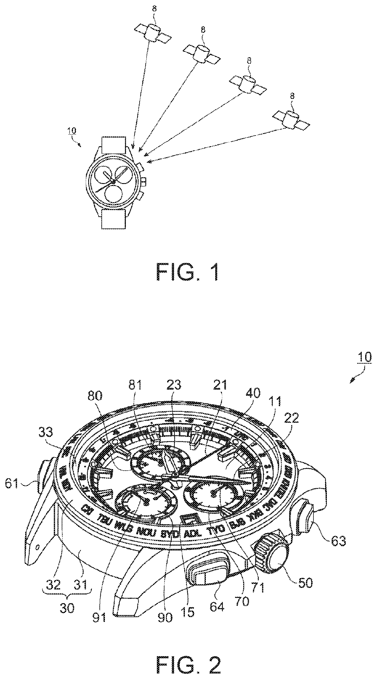
[0054]FIG. 1 is an overview of a GPS system including an electronic timepiece according to an embodiment of the invention. The outline of a GPS system whereby an electronic timepiece acquires positioning information and time information for the current location using satellite signals as external signals acquired from an external source (satellite) is described first below.

[0055]The electronic timepiece 10 in this example is a wristwatch that corrects the internal time by receiving signals (satellite signals) from GPS satellites 8, and displays the time on the opposite side (below called the face) as the side (below called the back) that is worn in contact with the skin. The GPS satellites 8 are navigation satellites orbiting the Earth on known orbits in space, and transmit a navigation message superimposed on a 1.57542 GHz carrier (L1 signal). ...

embodiment 2

[0158]A second embodiment of the invention is described next with reference to FIG. 13. This second embodiment uses the date indicator bridge 131 as a cover 200.

[0159]FIG. 13 is a partial section view of the electronic timepiece 10 according to the second embodiment of the invention in the radial direction through the antenna 110 (a section view corresponding to FIG. 11 of the first embodiment).

[0160]In the second embodiment, the dial bridge ring 126 does not have a cantilevered part 126g. The date indicator bridge 131 has a cantilevered part 131a (second cantilevered part) extending in plan view toward the outside case 30. The cantilevered part 131a extends to the outside circumference side from the date indicator 130 (to the side near the outside case 30).

[0161]The cantilevered part 131a of the date indicator bridge 131 has an overlap with the antenna 110 in plan view, and is disposed in section view so that the area where the cantilevered part 131a is disposed in the thickness di...

embodiment 3

[0166]A third embodiment of the invention is described next with reference to FIG. 14. This third embodiment describes a configuration using the dial bridge ring 126 and the date indicator bridge 131 as a cover 200 (a configuration in which the cover 200 includes the dial bridge ring 126 and date indicator bridge 131).

[0167]FIG. 14 is a partial section view of the electronic timepiece 10 according to the third embodiment of the invention in the radial direction through the antenna 110 (a section view corresponding to FIG. 11 of the first embodiment).

[0168]In this example, the end on the inside circumference side of the date indicator bridge cover 126g-3 part of the cantilevered part 126g of the dial bridge ring 126 in the first embodiment is shortened. The resulting space is then filled by the date indicator bridge 131.

[0169]More specifically, the thickness of the antenna cover 131c of the date indicator bridge 131 on the outside circumference side of the solar battery 135 is increa...


PUM

PropertyMeasurementUnit
timeaaaaaaaaaa
timeaaaaaaaaaa
timeaaaaaaaaaa

Abstract

Provided is technology that suppresses increasing the thickness of the electronic timepiece when a member is provided to obscure the area where the solar battery is not located above the antenna. An electronic timepiece has: an optically transmissive dial; a solar battery having a photovoltaic solar cell; an antenna disposed relative to the dial in the direction in which the external light is emitted, and configured to receive radio signals; and a cover member having a first part disposed between the dial and the antenna. In plan view, the antenna has a part that does not overlap the solar cell; the first part has a part that does overlaps the part of the antenna that does not overlap the solar cell; and in section view perpendicular, has an overlap between the first part and the solar battery.

Description

BACKGROUND1. Technical Field[0001]The present invention relates to an electronic timepiece.2. Related Art[0002]Electronic timepieces having a patch antenna or other type of antenna for receiving signals such as radio signals transmitted from satellites, and a solar battery, are known from the literature. Such electronic timepieces commonly have a transparent dial so that light can pass through the dial and be incident to the solar battery. The solar battery is located on the back cover side of the dial, and the antenna is located on the back cover side of the solar battery.[0003]To prevent a drop in reception sensitivity due to the solar battery being located above the antenna, the technology described in JP-A-2012-211895 provides a notch in the solar battery in the area above the solar battery. To prevent the notch from being visible through the transparent dial, a cover sheet is also provided between the solar battery and dial.[0004]The technology described in JP-A-2012-211895 dis...

Claims


Application Information

Patent Timeline
Patent Type & Authority Patents(United States)
IPC IPC(8): G04G17/04G04G17/08G04R60/12G04G19/00G04R20/02
CPCG04G17/08G04G19/00G04R60/12G04G17/04G04R20/02
Inventor SAWADA, AKIHIRO
Owner SEIKO EPSON CORP
Why Eureka
Try Eureka