
Flexible circuit board and display device

a flexible circuit board and display device technology, applied in the direction of circuit bendability/stretchability, printed circuit stress/warp reduction, printed circuit non-printed electric components association, etc., can solve the problems of flexible circuit board warpage, flexible circuit board thickening as a whole, disadvantageous routing, etc., to suppress the occurrence of warpage and suppress the increase of thickness

Active Publication Date: 2017-09-21
JAPAN DISPLAY INC
View PDF3 Cites 2 Cited by
  • Summary
  • Abstract
  • Description
  • Claims
  • Application Information

AI Technical Summary

Benefits of technology

The invention aims to provide a flexible circuit board that can prevent thickening and maintain its shape, and a display device that uses this circuit board.

Problems solved by technology

However, it has been found that warpage occurs in the flexible circuit board due to heat in mounting the electronic component.
For suppressing the occurrence of warpage, the reinforcing plate may be conceivably bonded to the other surface as disclosed in JP 2013-38154 A. In that case, however, the flexible circuit board is thickened as a whole, which is disadvantageous in terms of routing.

Method used


Image

  • Flexible circuit board and display device
  • Flexible circuit board and display device
  • Flexible circuit board and display device

Examples


Embodiment Construction

[0013]Hereinafter, the embodiment of the invention will be described with reference to the drawings. The disclosure is illustrative only. Appropriate modifications that will readily occur to those skilled in the art and fall within the spirit of the invention are of course included in the scope of the invention. For more clarity of description, the width, thickness, shape, and the like of each part may be schematically represented in the drawings, as compared with those in the embodiment. However, they are illustrative only and do not limit the interpretation of the invention. Moreover, in the specification and the drawings, elements similar to those described in relation to a previous drawing are denoted by the same reference numerals and signs, and a detailed description may be appropriately omitted.

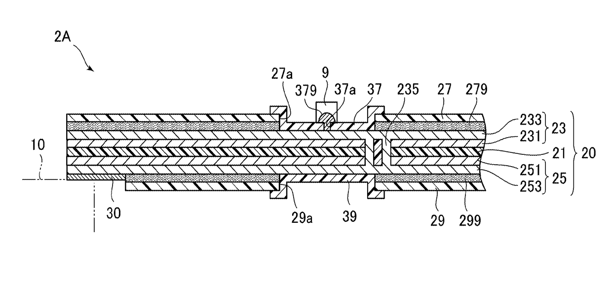
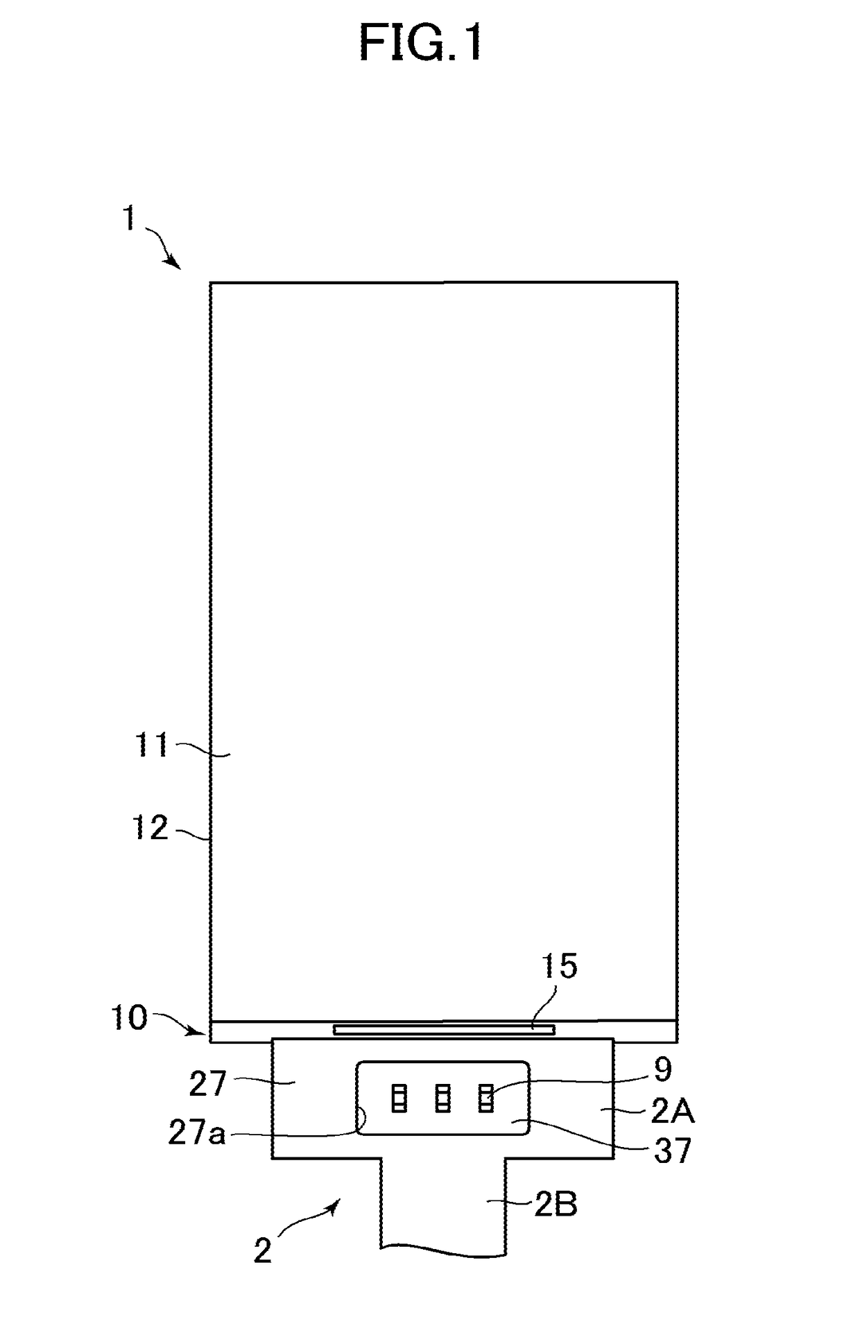
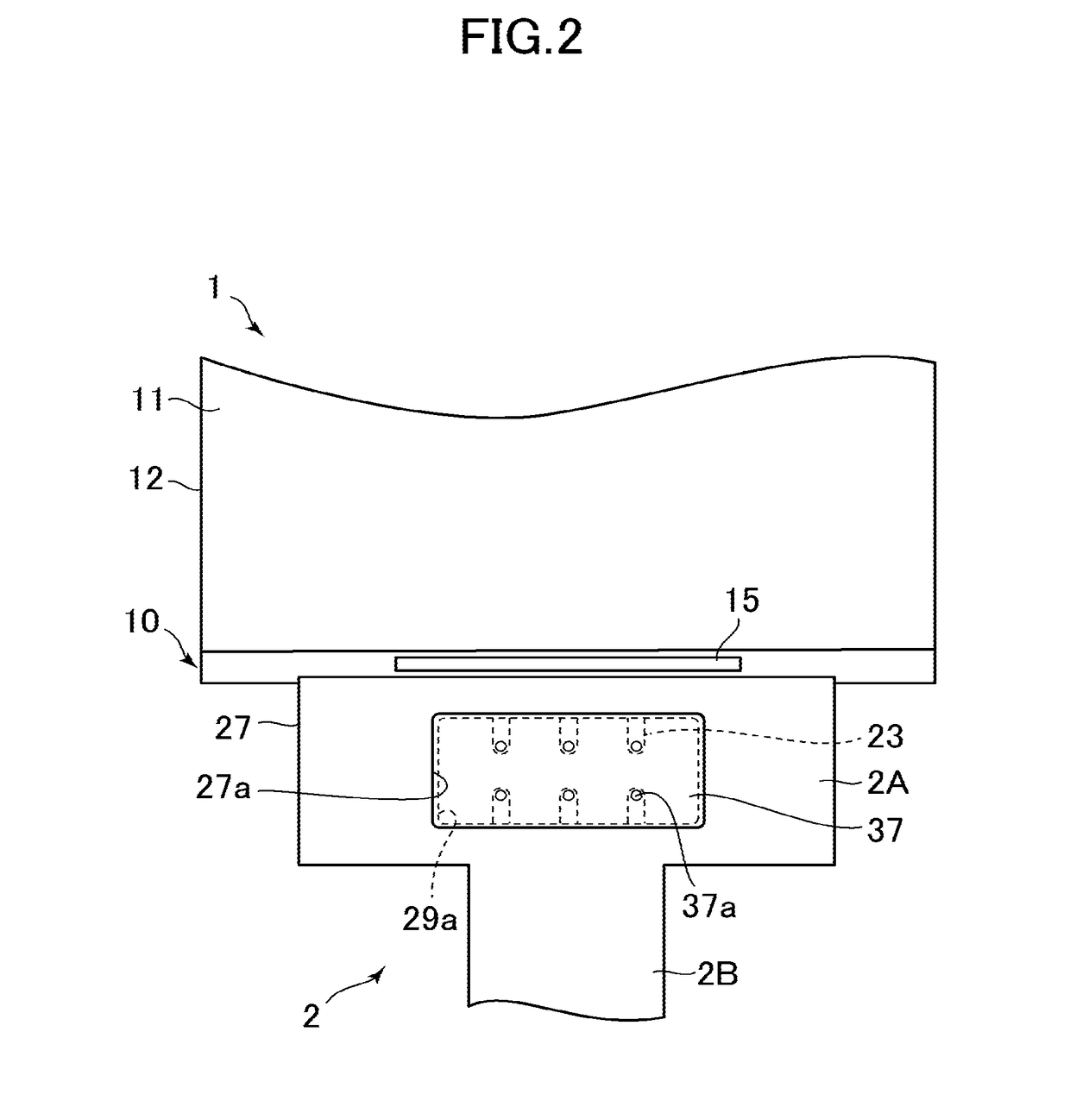
[0014]FIG. 1 is a plan view of a flexible circuit board 2 and a display device 1 according to the embodiment of the invention. FIG. 2 is an enlarged view of a main portion of FIG. 1. I...


PUM

PropertyMeasurementUnit
flexibleaaaaaaaaaa
thermal expansion coefficientaaaaaaaaaa
areaaaaaaaaaaa

Abstract

A flexible circuit board includes a base material including a first surface and a second surface opposite the first surface, the base material including a conductor layer, a first insulating film covering the first surface of the base material and formed with a first opening, a first insulating member formed inside the first opening and formed with a connection port to expose the conductor layer, the first insulating member having a thermal expansion coefficient smaller than that of the first insulating film, a second insulating film covering the second surface of the base material and formed with a second opening overlapping at least a portion of the first opening in a plan view, and a second insulating member formed inside the second opening and having a thermal expansion coefficient smaller than that of the first insulating film.

Description

CROSS-REFERENCE TO RELATED APPLICATION[0001]The present application claims priority from Japanese application JP2016-055701 filed on Mar. 18, 2016, the content of which is hereby incorporated by reference into this application.BACKGROUND OF THE INVENTION[0002]1. Field of the Invention[0003]The present invention relates to a flexible circuit board and a display device.[0004]2. Description of the Related Art[0005]JP 2013-38154 A discloses a flexible circuit board (FPC), on one surface of which an electronic component is mounted and to the other surface of which a reinforcing plate is bonded.SUMMARY OF THE INVENTION[0006]In recent years, it has been performed to provide a patterned cured resin product, called a resist, inside an opening formed in an insulating film at a surface layer of a flexible circuit board and then mount an electronic component on the patterned cured resin product. However, it has been found that warpage occurs in the flexible circuit board due to heat in mounting...

Claims


Application Information

Patent Timeline
Patent Type & Authority Applications(United States)
IPC IPC(8): H05K1/02H05K1/11H05K1/18
CPCH05K1/0281H05K1/189H05K2201/068H05K1/0271H05K2201/10128H05K1/115H05K1/118H05K2201/0154H05K2201/10681
Inventor NISHIMOTO, YUUKI
Owner JAPAN DISPLAY INC
Learn More