Piezoelectric driving vibratory feeder and piezoelectric element driving feeder

A vibrating feeding and piezoelectric driving technology, which is applied in the direction of electrical components, vibrating conveyors, piezoelectric effect/electrostrictive or magnetostrictive motors, etc., can solve the problem of higher overall height of the device, longer spring length, and surrounding Problems such as machine configuration relationship obstruction

Inactive Publication Date: 2002-11-20
SHINKO ELECTRIC CO LTD
View PDF0 Cites 17 Cited by
  • Summary
  • Abstract
  • Description
  • Claims
  • Application Information

AI Technical Summary

Problems solved by technology

However, when a piezoelectric element of the same length is attached to the above position, the spring length of the piezoelectric spring piece B' becomes longer, the ove...

Method used


Image

  • Piezoelectric driving vibratory feeder and piezoelectric element driving feeder
  • Piezoelectric driving vibratory feeder and piezoelectric element driving feeder
  • Piezoelectric driving vibratory feeder and piezoelectric element driving feeder

Examples


Embodiment Construction

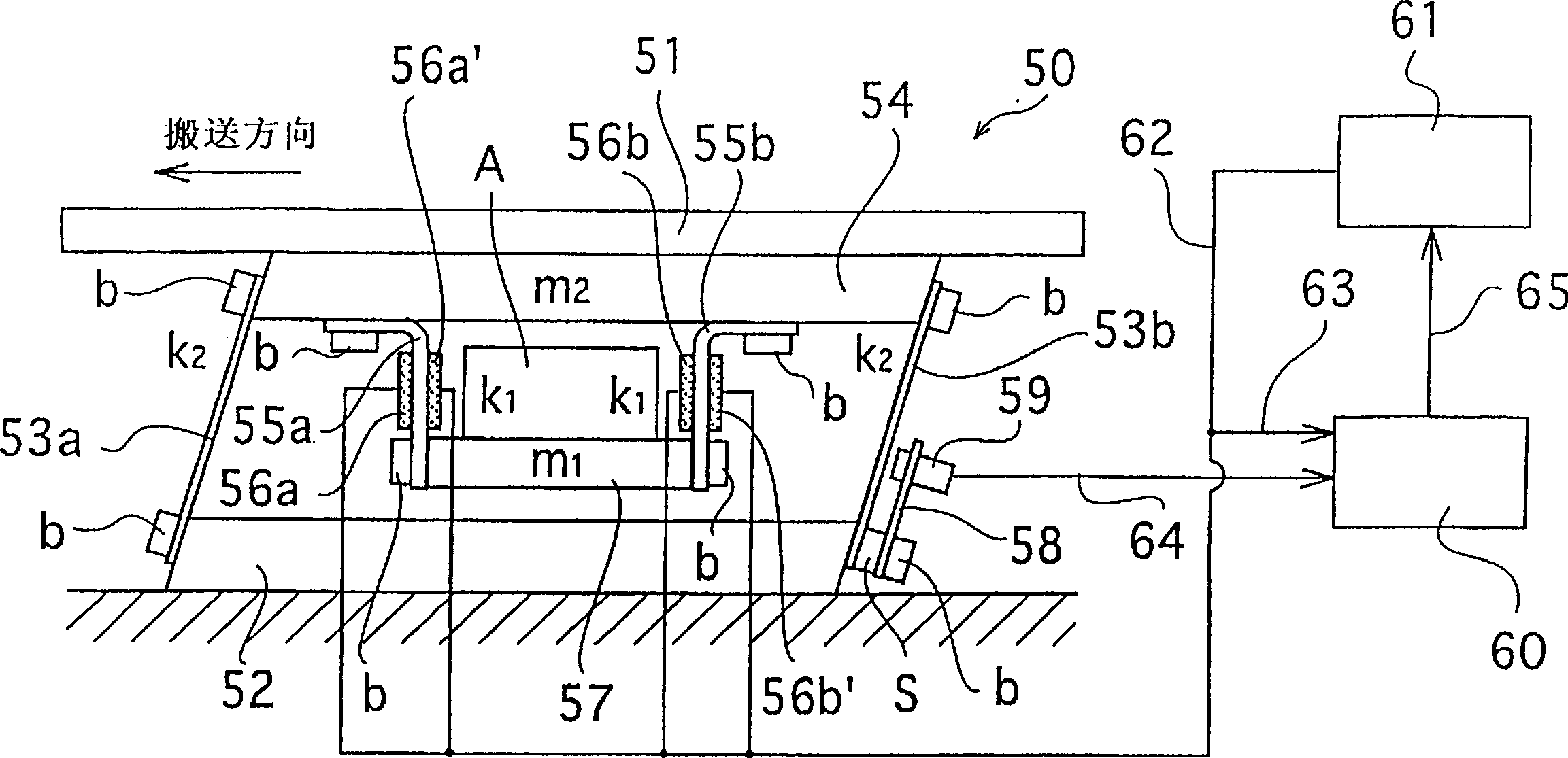
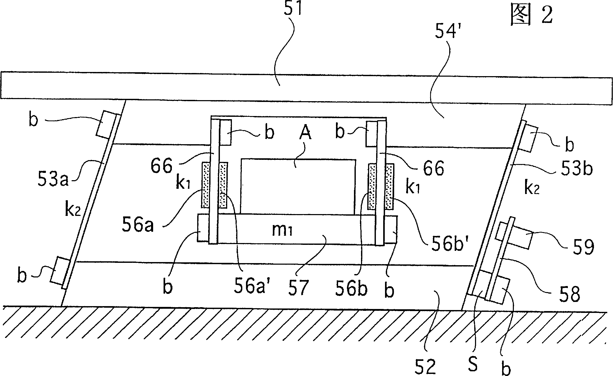
[0041] Below, refer to figure 1 A first embodiment of the present invention will be described.

[0042] exist figure 1 In the piezoelectric-driven vibrating feeder 50 of the present invention, the conveying trough 51 is combined with the base 52 through a pair of front and rear spring pieces 53a, 53b arranged obliquely. Moreover, the upper ends of the spring sheets 53a, 53b are fixed on the spring sheet mounting block 54 integrated with the delivery trough 51, whereby the delivery trough 51 is supported on the spring sheets 53a, 53b so that it can be substantially perpendicular to the spring sheet Vibrate in the direction of the longitudinal direction of 53a, 53b.

[0043] By bolt b, a pair of spring sheets 55a, 55b close to the reverse L shape are fixed below the spring sheet mounting block 54, and the piezoelectric elements 56a, 56a' and 56b, 56b' are pasted on the spring sheets 55a, 55b. two sides. Furthermore, according to the present invention, the common opposing m...


PUM


Abstract

A piezoelectric-driven vibrating feeder for the purpose of reducing the overall height of the device and applying only the original vibration necessary for conveying to the conveying tank. The feeder has a base vibratingly supported by a pair of front and rear first spring pieces The working mass body on the top, the opposing mass device combined with the working mass body through a pair of front and rear second spring pieces, the piezoelectric element pasted on at least one side of each of the aforementioned second spring pieces, by applying AC voltage, and make it flexurally vibrate on the aforementioned second spring piece, so that the aforementioned working mass body vibrates, thereby transporting the object on the working mass body, wherein the aforementioned opposing mass device is a single opposing mass body, and is fixed on respective one ends of the aforementioned second spring pieces.

Description

technical field [0001] The invention relates to a piezoelectric element-driven feeder formed by suspending a vibrating hammer on the bottom surface of a conveying tank, and a piezoelectric-driven vibrating feeder. Background technique [0002] As such a piezoelectric-driven vibrating feeder, a device as shown in FIG. 5 is disclosed in Japanese Patent No. 2762211. The carrier (use the terms used in this specification, the same below) 5 is supported by a carrier support 8 formed of a pair of front and rear vertical spring steels, and a base 3 is fixed at the lower end. The front and rear heights of the base 3 are different, that is, formed into a table shape, so the movable length of the carrier support body 8 used as a spring is different from the front to the rear. A pair of front and rear vibrating bodies 9 formed by pasting piezoelectric elements 1 on both sides of the elastic sheet 2 are fixed to the lower surface of the carrier body 5 . Is the so-called bimorph structu...

Claims


Application Information

Patent Timeline
IPC IPC(8): B65G27/08B65G27/24B65G27/26H02N2/00
CPCB65G27/08B65G27/24B65G27/26
Inventor 加藤一路藤井隆良斋藤伸浩佐藤雄志木村哲行村岸恭次
Owner SHINKO ELECTRIC CO LTD
Why Eureka
Try Eureka