Assemble comb-type bridge extension joint

An expansion device and assembled technology, applied in the direction of bridges, bridge parts, bridge construction, etc., can solve the problem of unsuitable expansion joint devices, and achieve the effect of eliminating unsafe hidden dangers, low cost and low height.

Inactive Publication Date: 2002-12-11
徐斌
View PDF2 Cites 13 Cited by
  • Summary
  • Abstract
  • Description
  • Claims
  • Application Information

AI Technical Summary

Problems solved by technology

[0006] The structures of the above two patents are also not suitable

Method used


Image

  • Assemble comb-type bridge extension joint
  • Assemble comb-type bridge extension joint
  • Assemble comb-type bridge extension joint

Examples


Embodiment Construction

[0022] The present invention will be further described in detail below with reference to the embodiments of the accompanying drawings.

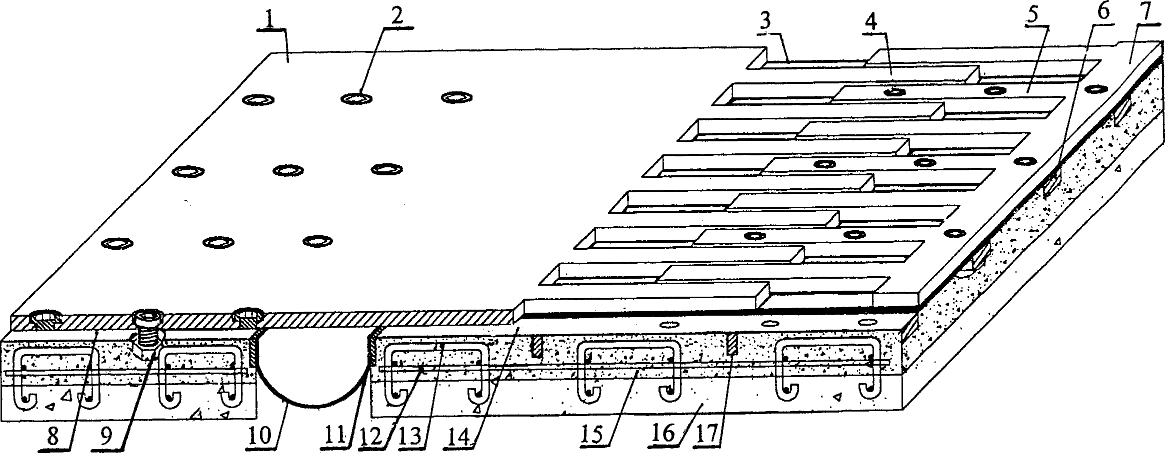
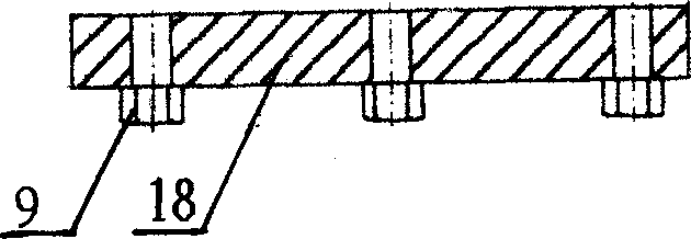
[0023] Horizontal support plate 6,18, for the elongated shape of 1~6 through holes 2 on the upper, lower end surface through hole 2 corresponding place, welding is fixed with nut 9, and through hole 2 number is determined by its length.

[0024] The vertical support plates 11, 17 are elongated.

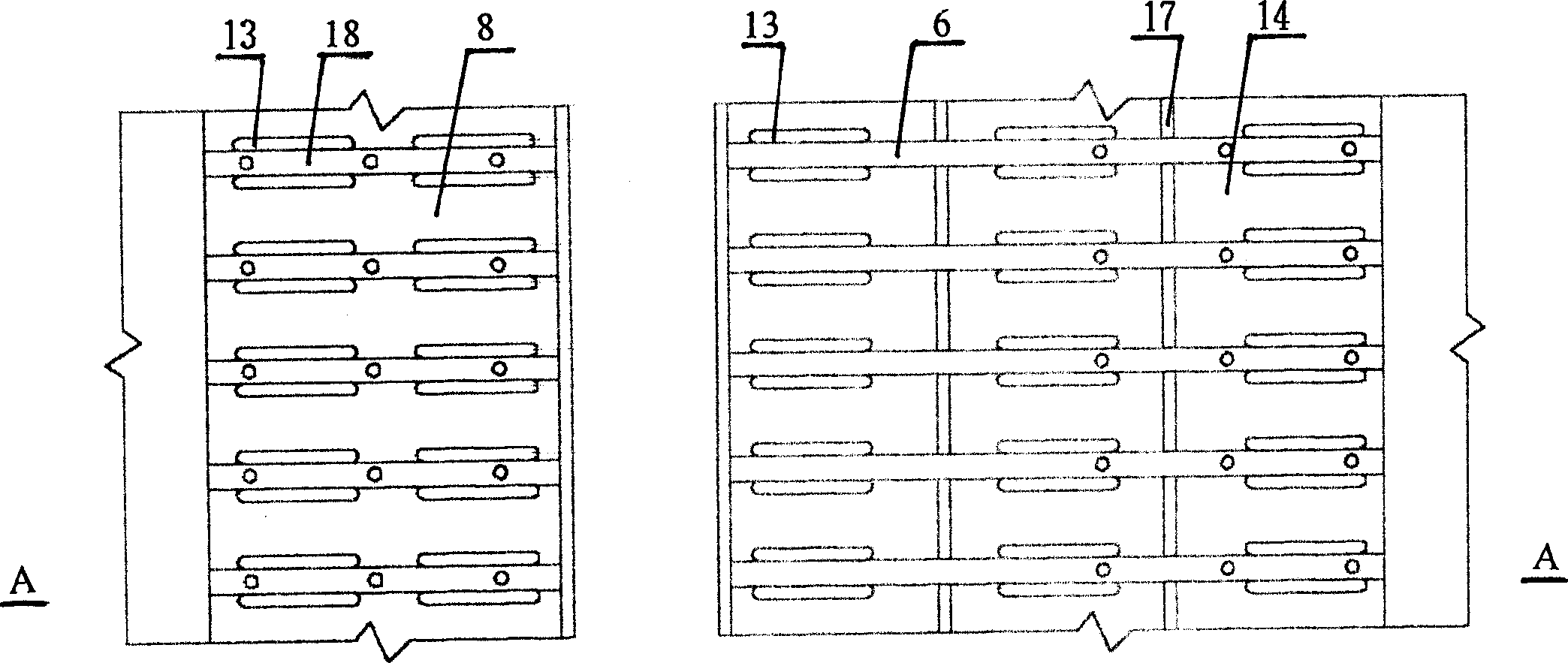
[0025] On both sides of the expansion joint, two steel bars 13 with horizontal and crack-proof mesh bars 12 are arranged in parallel in a group, arranged in sequence, embedded in the beam body 16, and a horizontal support plate 6, 18 is clamped therebetween. It is welded and fixed on both sides of steel bar 13. During construction, due to the dislocation caused by the pre-embedded steel bars 13, additional steel bars can be added to weld and fix the transverse support plates 6, 18 and the pre-embedded steel bars 13 into one for remediation.

[0026...


PUM


Abstract

The assembled comb-type bridge extension joint has a extension amount of 20-150 mm and is especially suitable for use in large highway bridge, sea-crossing bridge and city viaduct of extension amountover 160 mm. It includes two rubber plates in two ends, comb palte and anchor mechanism connected to form an integral. The comb plate consists of matched and toothed fixed board and moving board, theanchor mechanism has support tray fixed to the embedded bars, and the extension is completed by the moving comb board. The comb boards as wearing parts are easy to replace in maintenance.

Description

technical field [0001] The invention relates to an important device used in road and bridge construction. It is widely used in telescopic devices with a stretching amount of 20-150 mm, and is especially suitable for high-grade highway bridges and sea-crossing bridges with a stretching amount of more than 160 mm. The prefabricated comb-type bridge expansion device installed on the bridge and urban viaduct. Background technique [0002] In order to meet the requirements of bridge deformation, high-grade highways and bridges need to be equipped with telescopic devices at the joints during construction. With the development of transportation, the requirements for driving comfort, safety and reliability have become more and more High, the existing, traditional Maurer type and elastic seamless expansion device cannot meet the requirements of high-grade highways and bridges. [0003] Patent No. 97220451.2 "Large Displacement Bridge Expansion Joint Device" also provides a Maurer-ty...

Claims


Application Information

Patent Timeline
IPC IPC(8): E01D19/06
Inventor 徐斌
Owner 徐斌
Why Eureka
Try Eureka