Bridging member for concrete form walls

a technology of bridging member and concrete form, which is applied in the direction of walls, constructions, building components, etc., can solve the problems of inefficiency of both parts of this construction, labor-intensive and expensive piecemeal construction, and inherent in the wood frame part of the structure, so as to improve the strength and reinforcement grid, reduce the effect of material consumption

Inactive Publication Date: 2006-04-25
AIRLITE PLASTICS
View PDF188 Cites 71 Cited by
  • Summary
  • Abstract
  • Description
  • Claims
  • Application Information

AI Technical Summary

Benefits of technology

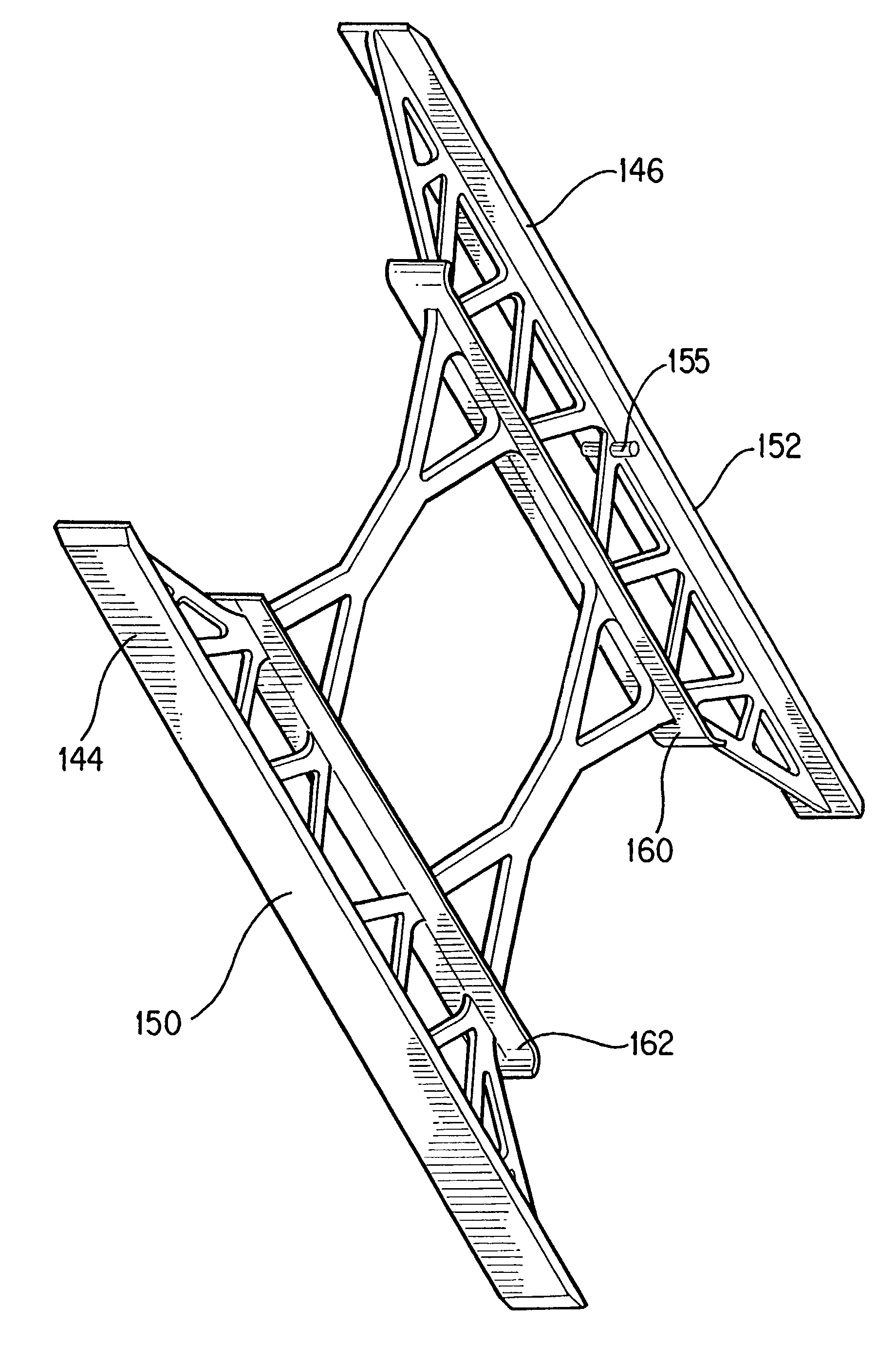
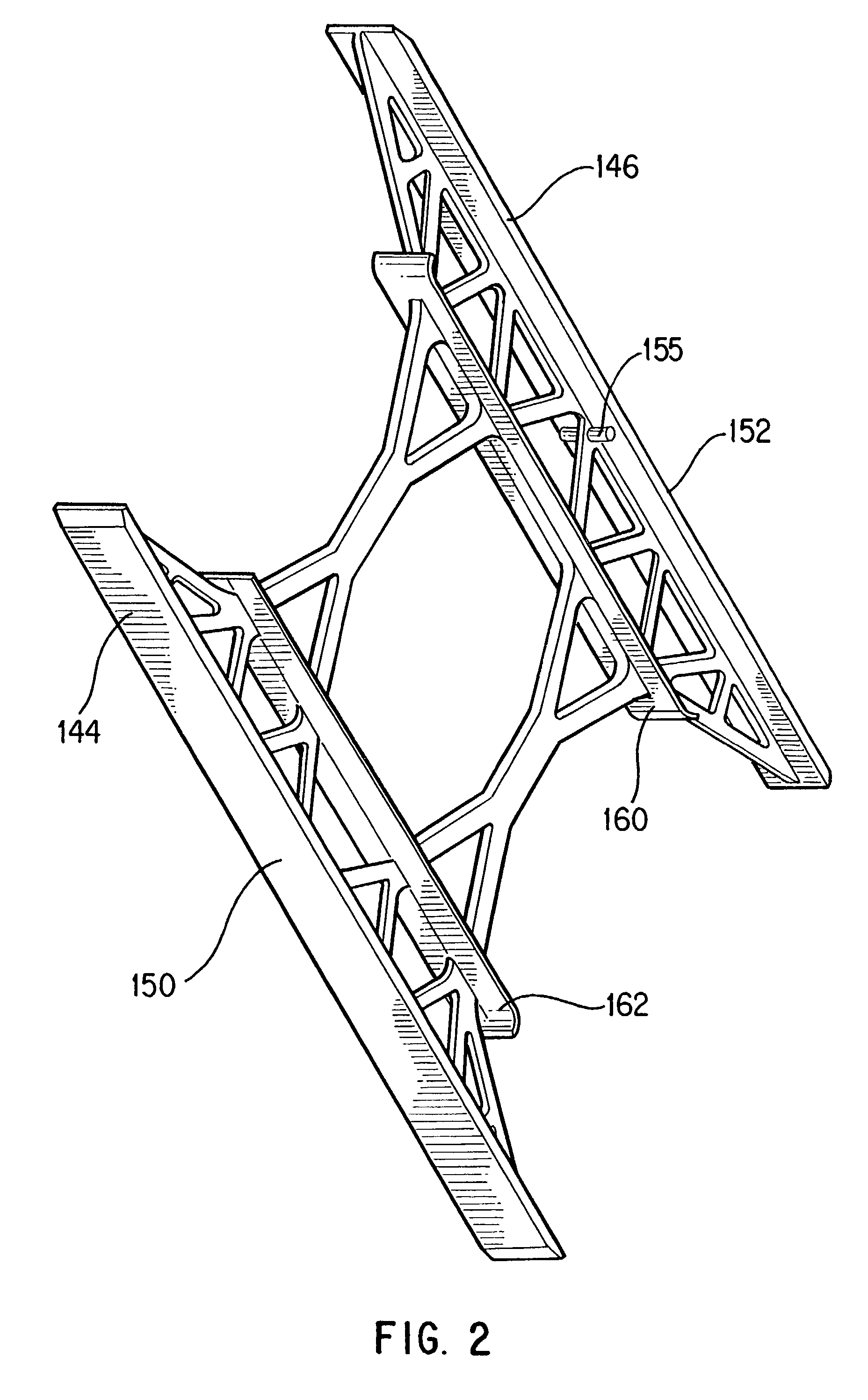
[0012]It has now been discovered that substantial advantages can be obtained where the building component used to build up an ICF wall includes bridging members that are engineered to combine an enhanced strengthening and reinforcing grid with a substantial reduction in material. Structural analysis of the bridging members has been performed to arrive at the invention using finite element analysis methods. The resulting structure of the bridging members achieves optimized strength from a minimized amount of material by the unique configuration of web members that form part of the bridging members. The web members of the invention are configured to use material in the most efficient manner such that the bridging member can resist larger loads or resist the same loads with less deflection than known structural members used to produce similar form walls.

Problems solved by technology

Clearly, both parts of this construction are inefficient.
It is time-consuming and wasteful of materials to have to remove the form walls after the concrete walls are poured.
The piecemeal construction, which is inherent in the wood frame part of the structure is labor-intensive and expensive.
While the component disclosed in this patent has numerous advantages, works well and has been commercially successful for a number of years, the bridging members used to connect the form walls do not make the most efficient use of the material from which they are constructed to resist lateral forces generated by the concrete or other building material poured in between the form walls.
When more material is used to form the structural members than is actually required to withstand tensile and other loads, the resulting form walls are unnecessarily expensive and heavy.
Existing ICF systems thus far proposed, while in many cases are very useful, suffer from these or other similar disadvantages.

Method used


Image

  • Bridging member for concrete form walls
  • Bridging member for concrete form walls
  • Bridging member for concrete form walls

Examples


Embodiment Construction

[0029]Reference will now be made in detail to preferred embodiments of the invention, examples of which are illustrated in the accompanying drawings.

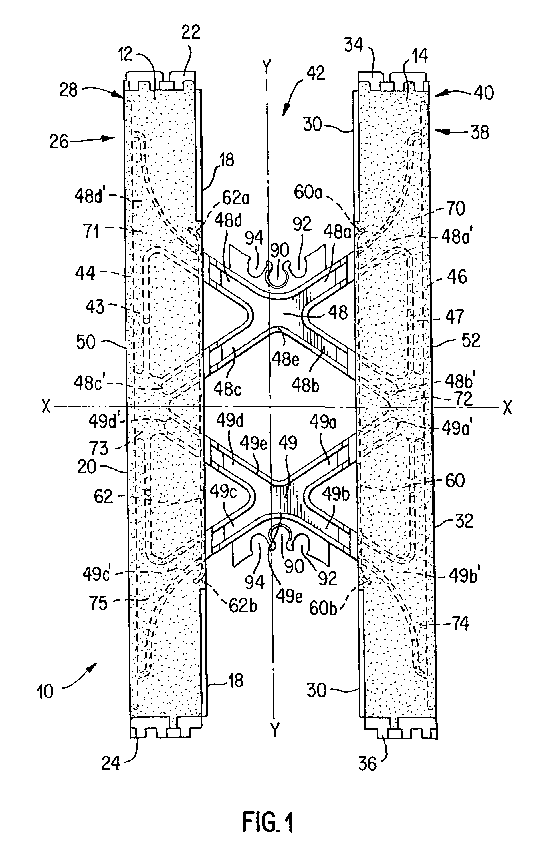
[0030]An ICF building component 10 shown in FIG. 1 comprises first and second insulating foam panels 12 and 14 secured together by at least two bridging members 42, which can generally be thought of as any structure used to connect the panels together consistent with the purposes and objectives of the invention.

[0031]Panel 12 has inner and outer surfaces 18 and 20 respectively, top and bottom 22 and 24 respectively, and first and second ends 26 and 28. Panel 14 has inner and outer surfaces 30 and 32, top and bottom 34 and 36, and first and second ends 38 and 40.

[0032]The panels 12 and 14 can be formed from fire retardant expanded polypropylene, polystyrene, polyethylene or other suitable polymers with expanded polystyrene commonly referred to as “EPS” being preferred. Subject to indentations and protrusions of minor dimensions, which ca...


PUM


Abstract

A building component having first and second high density foam panels and improved bridging members for connecting the panels that extend between and may be molded into the panels. The bridging members include a pair of elongated end plates oriented in a top to bottom direction of the panels, a pair of substantially identical web members joining the end plates and being substantially symmetrically disposed above and below a central horizontal axis of the bridging member, and a pair of strip members oriented in the top to bottom direction of the panels intersecting the web members. The web members have a unique configuration that maximizes load bearing capacity with a minimum amount of material. The strip members may abut against and be substantially flush with respective inner surfaces of the foam panels to assist in positioning and forming the panels during molding. Seating areas for positioning horizontally and/or vertically disposed rebar in predetermined positions are also provided.

Description

[0001]This is a continuation of application(s) application Ser. No. 09 / 937,440, which entered the National Stage in the U.S. under 35 U.S.C. 371 on Sep. 27, 2001 now abandoned from International Application Serial No. PCT / IB99 / 00672 filed Mar. 30, 1999, the contents of both applications being incorporated herein by reference.BACKGROUND OF THE INVENTION[0002]1. Field of the Invention[0003]This application relates to a building component of the type which is used to build up insulated concrete form (“ICF”) walls in building construction, and more particularly to an improved bridging member used to connect the opposed insulated panels of an ICF.[0004]2. Background of the Invention[0005]In conventional construction in North America, concrete walls are normally produced by constructing form walls, pouring concrete into the space between the form walls and, upon the setting of the concrete, removing the form walls. Finishing materials are then added to the concrete walls as required.[0006...

Claims


Application Information

Patent Timeline
Patent Type & Authority Patents(United States)
IPC IPC(8): E04B2/86
CPCE04B2/8617
Inventor COOPER, BRUCESCOTT, G. RICHIESCULTHORPE, ROBERT E.KNOWLES, GRAHAM A.
Owner AIRLITE PLASTICS
Why Eureka
Try Eureka