Siding for rolling stock

A technology for wall panels and vehicles, applied to railway car bodies, transportation and packaging, railway car body parts, etc., can solve problems such as troublesome maintenance operations, lack of preventive measures, and difficult loading and unloading of supporting shaft structures, and achieve the effect of ensuring traffic safety

Inactive Publication Date: 2003-01-01
NARITA SEISAKUSHO
View PDF0 Cites 3 Cited by
  • Summary
  • Abstract
  • Description
  • Claims
  • Application Information

AI Technical Summary

Problems solved by technology

[0005] In the aforesaid conventional wall board devices, the two movable wall boards 105, 106 only use the force applying devices 111, 112 to compress the fixed wall board 104, so, in the passage, the passengers may overcome the pressing force of the force applying devices. It is convenient to open the front end 109, 110 of the movable wall 105, 106, so that it is possible to contact the device arranged on the inner side of the wall from the opening. However, there are no sufficient preventive measures for this situation so far.
[0006] Have again, because the support shaft structure loading and unloading difficulty of aforementioned movable panel, its maintenance work troublesome

Method used


Image

  • Siding for rolling stock
  • Siding for rolling stock
  • Siding for rolling stock

Examples


Embodiment Construction

[0036] Embodiment of the invention

[0037] in accordance with Figure 1 to Figure 14 The examples illustrate embodiments of the invention.

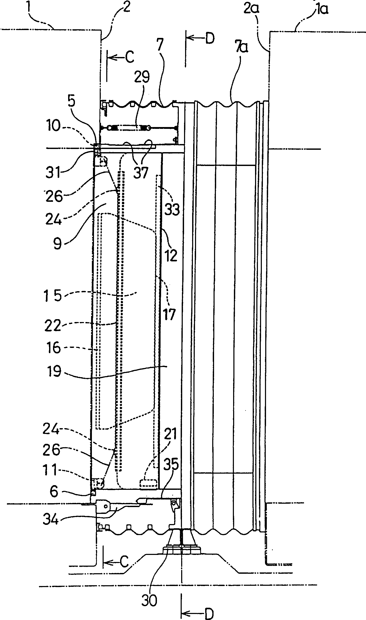
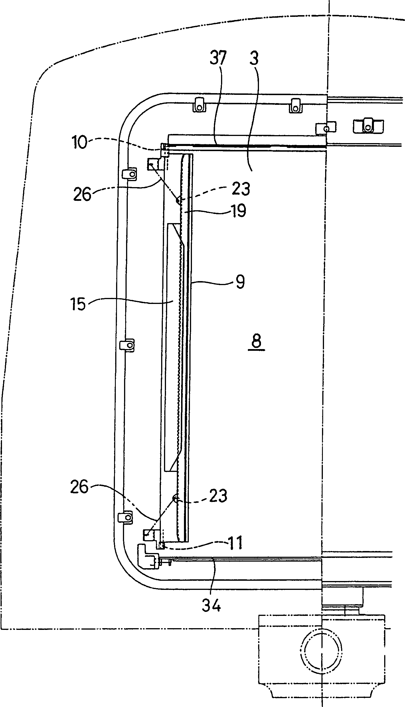
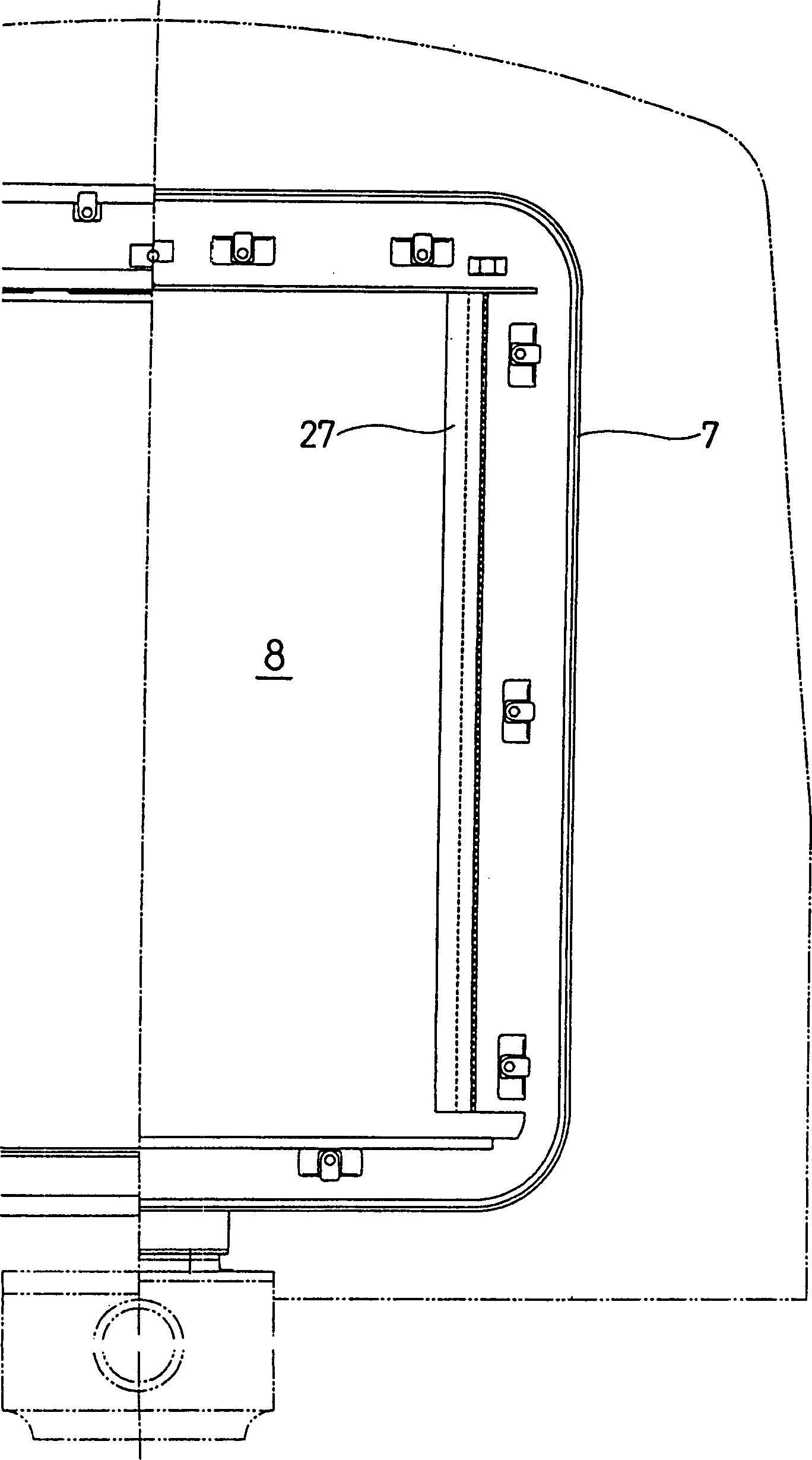
[0038] exist Figure 1 to Figure 13 In the first embodiment of the present invention, the side column portion 4 of the inlet and outlet 3 on the end face 2 of the connected side of the car body 1 (see Figure 4 , Figure 5 ) are fixedly provided with hinge seats 5, 6 with vertical shaft holes at the upper and lower positions of the side columns. On the side portion parallel to the passage direction A-B of the passage 8 surrounded by the shed 7, that is, on one side of the carriage body 1, a side rotating wall plate 9 constituting the side wall is erected. The hinge shafts 10, 11 protruding from the vertical direction of the upper and lower ends of the part are rotatably fitted in the aforementioned hinge seats 5, 6, and the rotating wall plate 9 can rotate horizontally around the hinge shafts 10, 11. The rotating wall plate 9 is for...


PUM


Abstract

To prevent passengers from opening a rotary panel and touching a device within the panel in the device formed with a side panel by allowing the rotary panel to abut on a surface side of a center panel. SOLUTION: One rotary panel 9 rotating with a vertical shaft 11 arranged on an end surface part of a vehicle body 1 as a center is provided on the one vehicle body 1 side. The other rotary panel 9a rotating with a vertical shaft 11a arranged on an end face part of a vehicle body 1a as a center is provided on the other vehicle body 1a side. Locking plates 15 and 15a are fixed with prescribed gaps 14 and 14a by being located on each side opposite to a through passage 8 side to both of the rotary panels 9 and 9a. A center panel 19 is arranged between both of the rotary panels 9 and 9a by slidably inserting front and rear parts 20 and 20a of the direction of the through passage into the gaps 14 and 14a on both the rotary panels 9 and 9a sides. The front part 20 of the center panel 19 is energized to the one vehicle body 1 side and the rear part 20a is energized to the other vehicle body 1a side.

Description

technical field [0001] The present invention relates to a panel arrangement for use in a rolling stock walkway, and more particularly, the invention relates to a panel arrangement for forming side walls of a rolling stock walkway. Background technique [0002] The outer circumference of the passageway at the connecting part of the rolling stock (carriage) is covered with a bellows, and according to the necessity of improving the safety, sound insulation and comfort of passing in the connecting part and improving the same aesthetics as the interior wall of the passenger compartment, the rigid The wall panels are arranged in parallel on the inner side of the bellows. [0003] The passage of such a wall board often causes the two rolling stock connected to it to vibrate up and down relative to each other, and when the rolling stock passes through the S-shaped curve, the mutual offset between the rolling stock is large. [0004] Therefore, in the past, Publications No. 3-26048 ...

Claims


Application Information

Patent Timeline
IPC IPC(8): B61D17/20B61D17/00B61D17/08
CPCY02T30/34Y02T30/00
Inventor 波多野干夫
Owner NARITA SEISAKUSHO
Why Eureka
Try Eureka