Connector and its mfg. method

A technology of connectors and connecting parts, applied in connection, fixed connection, printed circuit manufacturing, etc., can solve problems such as incomplete connection between terminals and electronic circuits, high total cost of manufacturing connectors, and complicated manufacturing process

Inactive Publication Date: 2003-02-19
MORUDETABUKU
View PDF0 Cites 15 Cited by
  • Summary
  • Abstract
  • Description
  • Claims
  • Application Information

AI Technical Summary

Problems solved by technology

This can lead to an incomplete connection between the terminal and the electronic circuit when the solder ball is melted
[0004] Solder balls themselves become expensive to manufacture because they must be precisely formed
Since it is necessary to en

Method used


Image

  • Connector and its mfg. method
  • Connector and its mfg. method
  • Connector and its mfg. method

Examples


Embodiment Construction

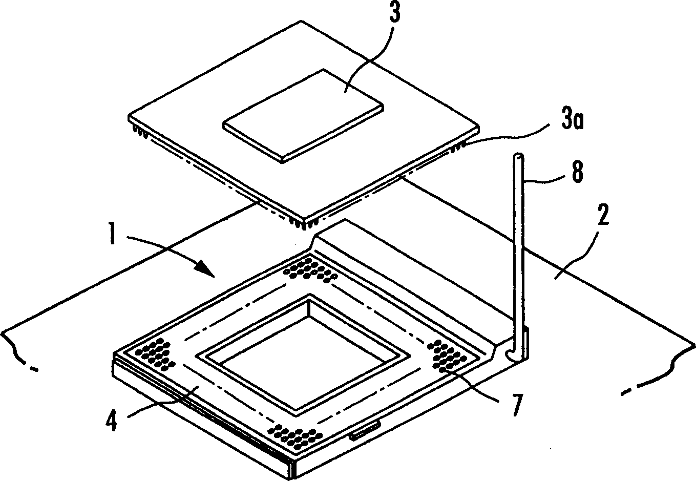
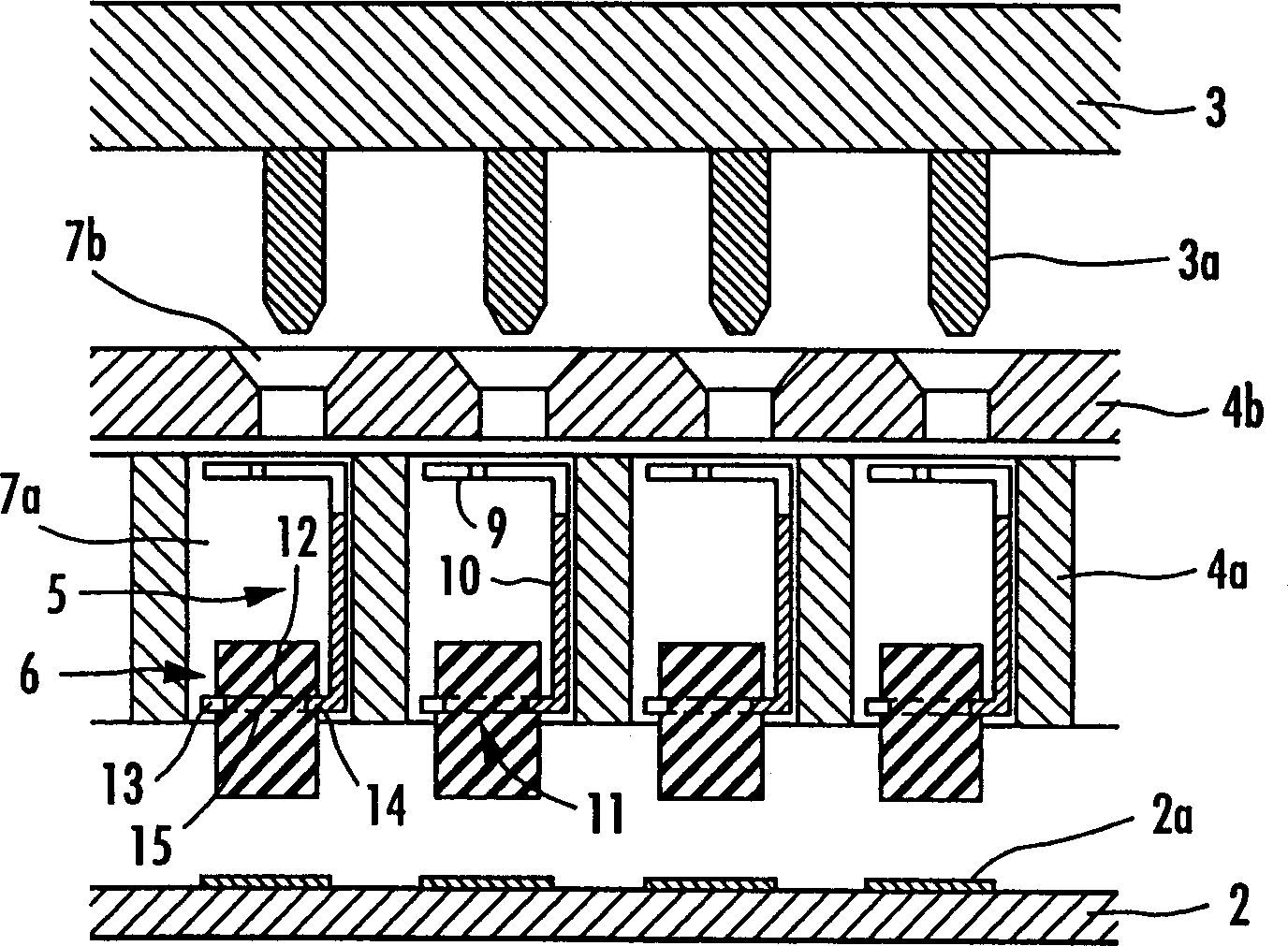
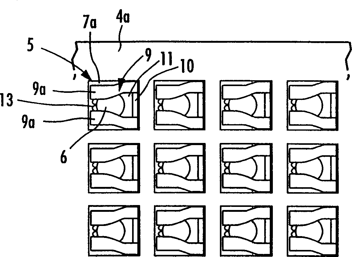
[0064] refer to Figure 1 to Figure 1 9. Describe a typical connector embodying the present invention. figure 1 is a schematic diagram of a typical connector embodying the invention, figure 2 is an enlarged fragmentary cross-sectional view of a connector according to a first embodiment of the present invention, image 3 is a partial plan view showing the internal state of the first embodiment, Figure 4 is a schematic diagram showing terminals of the connector according to the first embodiment, Figure 5a and 5b are schematic diagrams showing terminals of the connector according to the second embodiment, Figure 6a to 6c are schematic diagrams showing a method of fixing solder in a terminal, Figure 7 is a schematic diagram showing the process of improving coplanarity at the solder tip, Figure 8a to 8c are schematic diagrams showing connection states between terminals on the circuit board and electronic circuits according to this embodiment and a comparative example, ...


PUM


Abstract

The invention provides a connector which is easily manufactured and connects a circuit board in good condition. The connector according to the invention is a CPU socket to be surface-mounted on a circuit board 2, comprising a terminal 5 attached inside an internal case 4a made of an insulating material and a solder 6 fixed to the terminal 5. A connecting section 11 of the terminal 5 is provided with a pair of bar-like pieces 12, and has first claw sections 13 and a second claw section 14. In order to fix the solder 6 to the connecting section 11, tip ends of the first claw sections 13 are caulked by bending so that the tip ends contact with each other. The connecting section 11 is provided with an internal passage 15 connecting the upper and lower sides thereof. The solder 6 does not come off the terminal 5 because the solder 6 is attached to the internal case 4a after fixed to the connecting section 11 of the terminal 5 by caulking. In addition, it is easy to improve coplanarity of the tip end of each solder 6 because a length of the solder 6 protruding from the connecting section 11 is adjustable by changing the caulking position of the solder 6.

Description

technical field [0001] The present invention relates to a connector for mounting an integrated circuit on a circuit board, or for connecting one circuit board to another circuit board, and a method of making such a connector. Background technique [0002] Ball grid type (hereinafter referred to as BGA type) connectors are often used as a tool for mounting integrated circuits or one circuit board on another circuit board. This BGA type connector includes: a housing formed of insulating material and placed on a circuit board, a through hole vertically penetrating the housing, and a terminal, the terminal passes the pin attached in the through hole as a thermally fused conductive A solder ball of material that is electrically connected to an electronic circuit on a circuit board. This solder ball is attached to the recessed portion where the through hole faces the circuit board. In a sense, the solder ball is partially welded to the lower end of the terminal and attached. Th...

Claims


Application Information

Patent Timeline
IPC IPC(8): H01R24/00H01R33/76H01R43/00H01R43/20H01R107/00H05K3/34
CPCH01R12/716H05K3/3426H01R12/57Y02P70/50H01R13/6581
Inventor 竹内忍
Owner MORUDETABUKU
Why Eureka
Try Eureka