Rolling mill and method for operating same

A rolling mill and roll technology, applied in the field of operating the rolling mill, can solve the problems of low horizontal dynamic stiffness, hindering high-efficiency rolling, etc., and achieve the effects of improving accuracy, preventing rolling mill vibration, and reducing impact force

Inactive Publication Date: 2003-03-12
MITSUBISHI HEAVY IND LTD
View PDF3 Cites 8 Cited by
  • Summary
  • Abstract
  • Description
  • Claims
  • Application Information

AI Technical Summary

Problems solved by technology

If rolling is performed with high rolling forces and high reduction rates in the strip thickness while the horizontal dynamic stiffness of the mill is low, friction occurs in the housing or work rolls which may be caused by friction between the rolled strip and the work rolls. The huge vibration generated (hereinafter referred to as rolling mill vibration), which hinders high-efficiency rolling

Method used


Image

  • Rolling mill and method for operating same
  • Rolling mill and method for operating same
  • Rolling mill and method for operating same

Examples


no. 1 approach

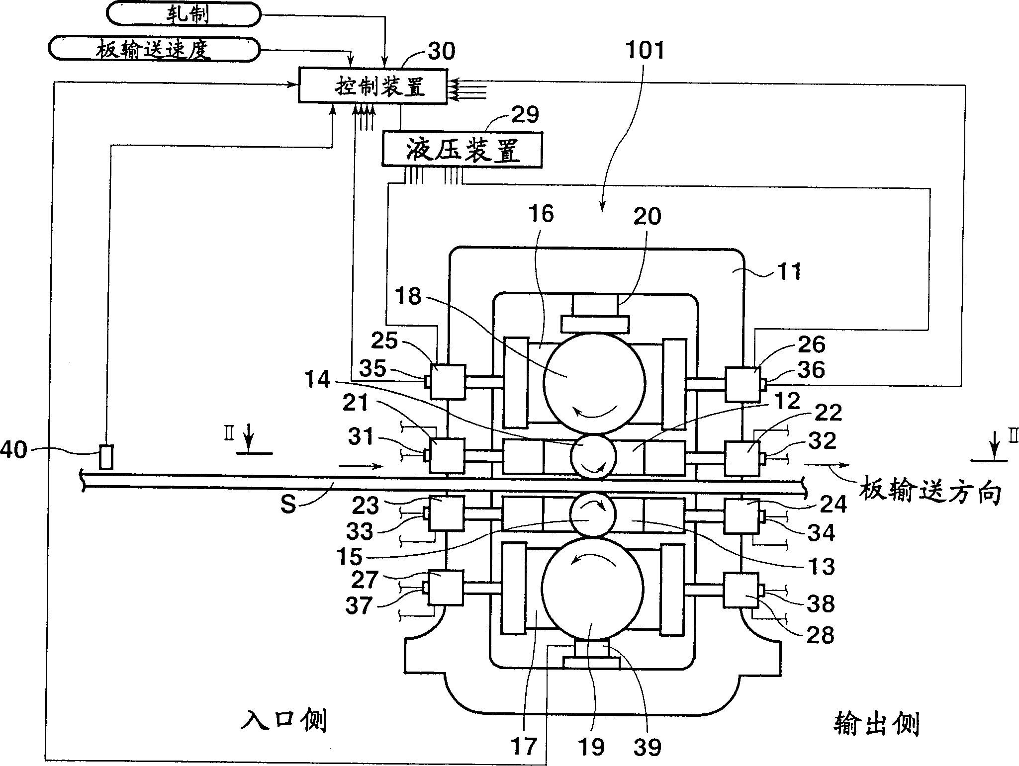
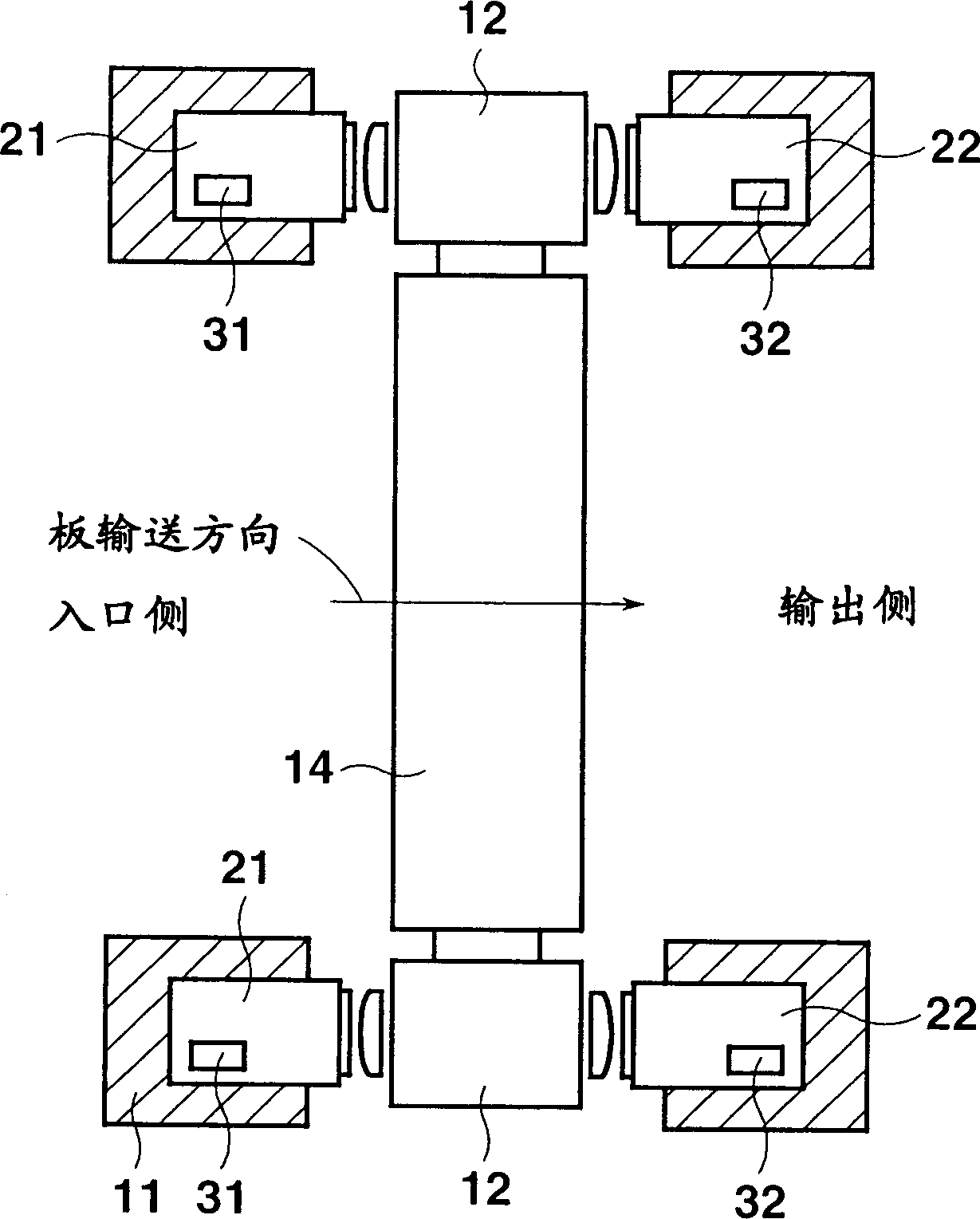
[0030] Such as figure 1 with 2 As shown in , in a rolling mill 101 according to the first embodiment, a pair of upper and lower work roll chocks 12 and 13 are supported in a housing 11 . Shaft portions of a pair of upper and lower work rolls 14 and 15 are rotatably supported by upper and lower work roll chocks 12 and 13, respectively, and the upper and lower work rolls 14 and 15 are opposed to each other. A pair of upper and lower backup roll chocks 16 and 17 are supported above and below the upper and lower work roll chocks 12 and 13 . Shaft portions of a pair of upper and lower backup rolls 18 and 19 are rotatably supported by upper and lower backup roll bearing housings 16 and 17, respectively. The upper backup roll 18 and the lower work roll 14 face each other, and the lower backup roll 19 and the lower work roll 15 face each other. In the upper part of the archway 11 there is a reduction device 20 for applying a rolling force on the upper work roll 14 by means of the u...

no. 2 approach

[0048] In the method for operating a rolling mill according to the second embodiment, the control device 30 controls the hydraulic device 29 such that before the tail end portion of the rollable material S passes between the work rolls 14 and 15, the hydraulic cylinders 21 to 28 will The pressure applied to the roll chocks 12 , 13 , 16 , 17 is set higher, and after the rollable material S passes between the work rolls 14 and 15 , the pressure is set lower.

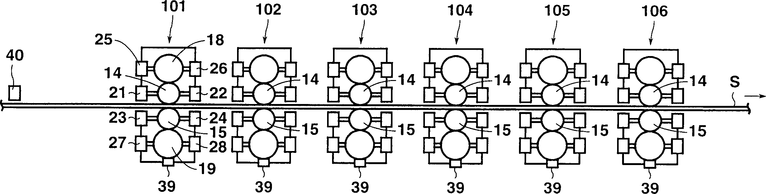
[0049] That is, as in image 3 with 5 As shown in , the rolling of the rollable material S by the rolling mill 101 is nearly completed, and the end detection sensor 40 detects the tail end portion of the rollable material S. In this case, the control device 30 at time t 6 The hydraulic device 29 is controlled to increase the operating oil pressure of the hydraulic cylinders 21 to 28 at a predetermined time after detection by the end detection sensor 40 . at time t 7 , the working oil pressure of the hydraulic cylinders...


PUM


Abstract

The invention relates to a rolling mill and method for operating same. Hydraulic cylinders are provided in a housing so as to be opposed to work rolls and backup rolls. Before a front end portion of a rollable material is engaged between the work rolls, the working oil pressure of the hydraulic cylinders is set at a high pressure value to make a pressing force on roll chocks high. After the rollable material is completely engaged between the work rolls, the working oil pressure of the hydraulic cylinders is set at a low pressure value to make the pressing force on the roll chocks low.

Description

[0001] Japanese Patent Application No. 2001-234654 filed on Aug. 2, 2001 including specification, claims, drawings and abstract is incorporated herein by reference in its entirety. technical field [0002] The present invention relates to a rolling mill for rolling a strip or the like passing between upper and lower rolls to a predetermined thickness and a method of operating the same. Background technique [0003] In a common rolling mill, the upper and lower work rolls are rotatably supported in the archway by means of work roll chocks, and the upper and lower work rolls face each other. The upper and lower support rolls are also rotatably supported in the archway by means of the support roll chocks, and the upper and lower support rolls are opposite to the upper and lower work rolls. In the upper part of the archway there is a reduction device for applying a rolling load on the upper work rolls by means of the upper back-up rolls. [0004] Therefore, the strip is fed fro...

Claims


Application Information

Patent Timeline
Patent Type & Authority Applications(China)
IPC IPC(8): B21B13/14B21B13/02B21B31/02B21B31/32B21B37/00
CPCB21B2013/025B21B13/023B21B31/02B21B31/32B21B37/007B21B13/14
Inventor 山本干朗东尾笃史古元秀昭
Owner MITSUBISHI HEAVY IND LTD
Why Eureka
Try Eureka