Dynamic shock-absorber in CRT

A technology of cathode ray tube and shock absorber, applied in the direction of cathode ray tube/electron beam tube, discharge tube, electrical components, etc., can solve the problems of unsuitability for mass production and high production cost

Inactive Publication Date: 2003-03-12
LG PHILIPS DISPLAY KOREA CO LTD
View PDF1 Cites 0 Cited by
  • Summary
  • Abstract
  • Description
  • Claims
  • Application Information

AI Technical Summary

Problems solved by technology

Such a component is not suitable for mass production due to its high production costs and defects in the crash tests of cathode ray tubes

Method used


Image

  • Dynamic shock-absorber in CRT
  • Dynamic shock-absorber in CRT
  • Dynamic shock-absorber in CRT

Examples


Embodiment Construction

[0051] Detailed description of the preferred embodiment

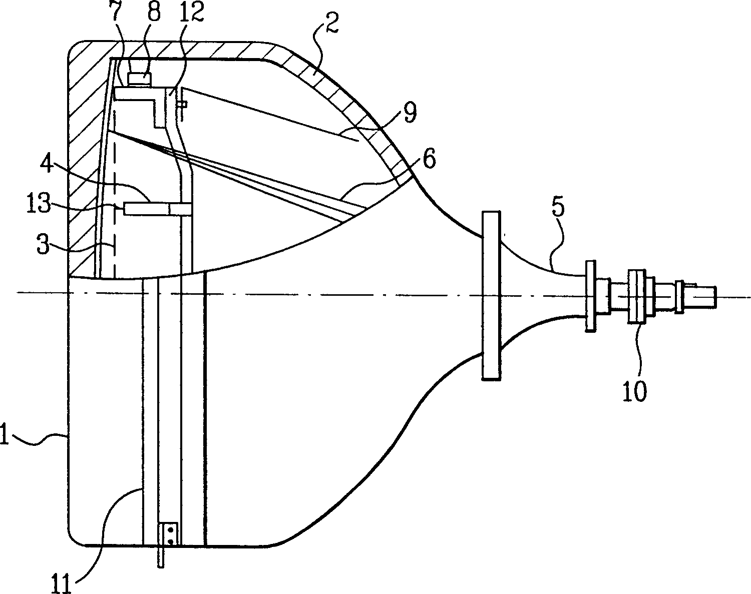
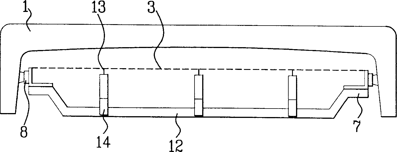
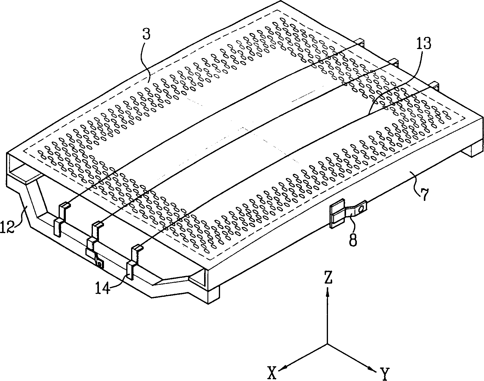
[0052] Referring to the details of the preferred embodiments of the present invention, the embodiments will be described in conjunction with the accompanying drawings. The dynamic damper in the cathode ray tube of the present invention will be referred to Figure 8 to Figure 10 Be explained.

[0053] The dynamic damper in the cathode ray tube of the present invention includes a base portion 110 and a vibration damping portion 120 . The base part 110 bears the vibration of the shadow mask 3, connects the vibration damping part 120 to the base part 110, and adjusts the natural frequency of the vibration damping part 120 to the natural frequency of the shadow mask 3, thereby actually absorbing the vibration. Preferably, the base part 110 and the vibration-damping part 120 are integrally made by stamping or sheet metal process. Also, it is preferable to manufacture the base portion 110 and the damping portion 120 from th...


PUM


Abstract

Dynamic vibration absorber in a CRT having a shadow mask fastened to an inside surface of a panel by main frames, including a base part to be fitted to a non-effective surface of the shadow mask, and a vibration absorbing part having one end connected to the base part and the other end designed to make no contact with the shadow mask and the main frame, thereby attenuating vibration of the shadow mask.

Description

[0001] This application claims priority from Korean Patent Application No. P2001-52569 filed on Aug. 29, 2001, which is hereby incorporated by reference. technical field [0002] The present invention relates to a cathode ray tube (CRT), in particular to a dynamic damper in a cathode ray tube, which can effectively weaken the shadow mask vibration caused by external impact, and the natural frequency of the dynamic damper is almost Does not change with temperature changes. Background technique [0003] FIG. 1 illustrates the structure of a related art cathode ray tube. [0004] There is a red, green and blue fluorescent film layer coated on the panel at the rear end of the panel 1, and an electron gun for emission is sealed inside the funnel 2, and the electron gun 6 is welded on the funnel 2. Installed on the inner surface of the panel 1 is a shadow mask 3 having a plurality of slits for passing electron beams, a deflection coil 5 and a magnet 10 installed on the outer surf...

Claims


Application Information

Patent Timeline
Patent Type & Authority Applications(China)
IPC IPC(8): H01J29/02H01J29/07
CPCH01J2229/0744H01J29/07H01J29/02
Inventor 李昊俊
Owner LG PHILIPS DISPLAY KOREA CO LTD
Why Eureka
Try Eureka