Fan with dustproof device

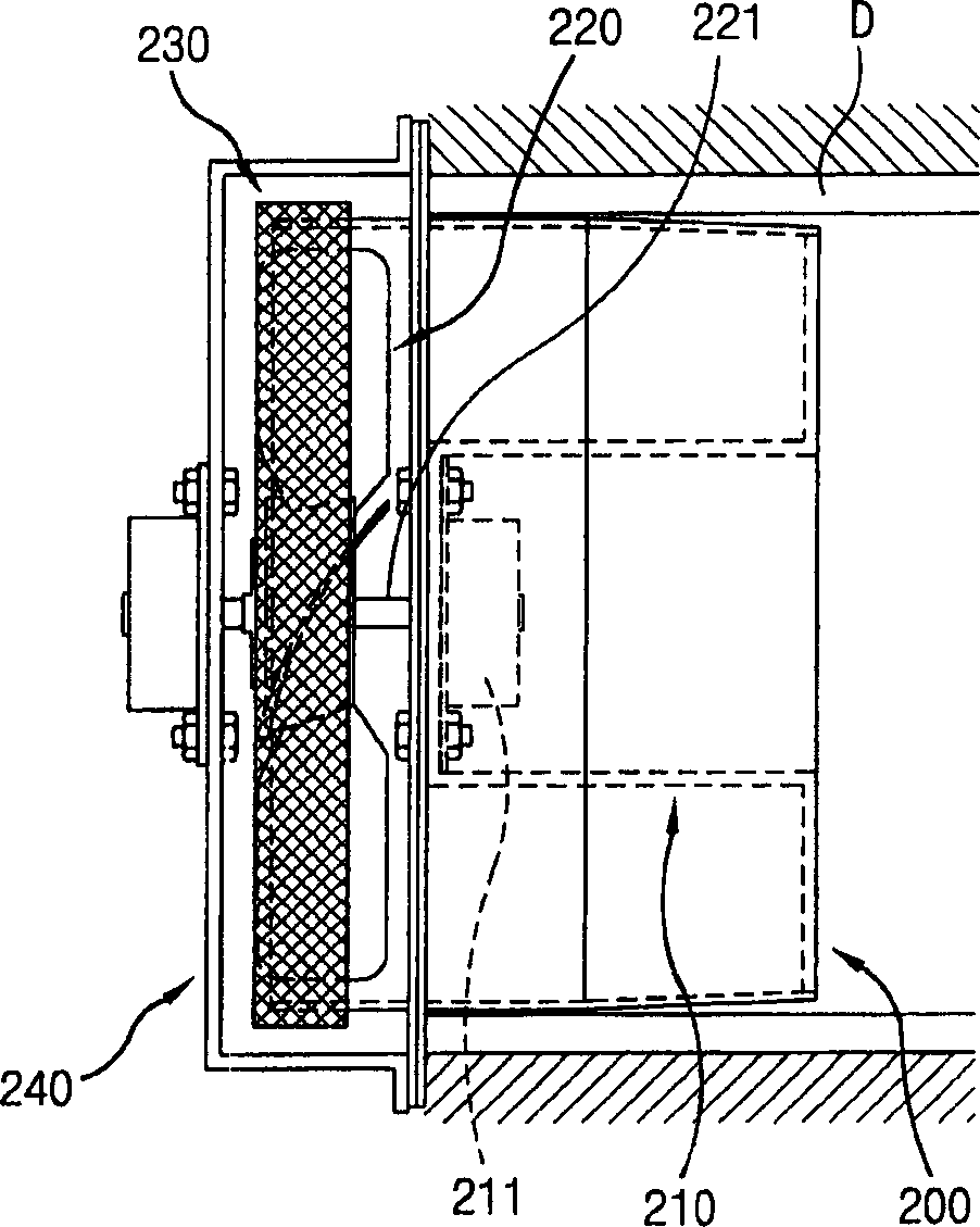
A dust-proof device and fan technology, which is applied to lighting devices, parts of pumping devices for elastic fluids, ventilation systems, etc., can solve the problem that the fixed state of the cylindrical dust-proof member 230 cannot be stabilized, and the roundness and assembly accuracy are not stable. Balance, structural complexity and other issues

Inactive Publication Date: 2003-03-19
LG ELECTRONICS INC
View PDF1 Cites 7 Cited by
  • Summary
  • Abstract
  • Description
  • Claims
  • Application Information

AI Technical Summary

Problems solved by technology

[0030] But, because the cylindrical dustproof member 230 is fixedly connected on the rotating shaft 221 of the propeller 220, so due to the effect of the rotating shaft 221, the fixed state of the cylindrical dustproof member 230 will not be stable.
[0031] In addition, an eccentricity will be generated between the propeller 220 and the cylindrical dustproof member 230 connected to the rotating shaft 221 of the propeller 220 due to the unevenness caused by roundness and as

Method used


Image

  • Fan with dustproof device
  • Fan with dustproof device
  • Fan with dustproof device

Examples


Example Embodiment

[0051] Hereinafter, preferred embodiments of the present invention will be described in detail, and examples of these preferred embodiments are shown in the accompanying drawings.

[0052] Figure 5 Is a cross-sectional view of a fan with a dustproof device according to the first embodiment of the present invention, and Figure 6 Yes Figure 5 A plan view of the fan according to the first embodiment of the present invention.

[0053] As in Figure 5 with 6 As shown in the first embodiment of the present invention, a fan with a dust-proof device includes: a housing 400 having a passage (F); a rotary drive unit (M), the rotary The drive unit (M) is installed inside the housing 400; blades 412, which are placed in the passage (F) and connected to the rotation shaft 411 of the rotary drive unit (M) for rotation; and A dust-proof member 430 installed at the entrance 420 of the passage (F) to cover the entrance 420 of the passage (F) and is integrally connected to the blade 412 so as t...


PUM


Abstract

A fan having a dust-proof apparatus includes: a casing having a passage; a rotation driving unit installed inside the casing; a plurality of blades positioned in the passage and coupled to a rotational shaft of the rotation driving unit so as to be rotated; and a dust-proof member installed at an entrance of the passage to cover the entrance of the passage, and integrally coupled to the blades so as to be rotated together with the blades. Since insects or big dusts can be prevented from being introduced according to an air flowing generated as the blades are rotated, and the coupling state between parts is firm. In addition, since the eccentricity is minimized, the parts are not damaged, and as a noise generation is restrained, so that reliability can be heightened.

Description

technical field [0001] The present invention relates to a fan, and in particular to a fan with a dust-proof device, which is installed at the suction port of the fan and can prevent insects or dust from being introduced together with the air. Background technique [0002] A fan for generating a fluid flow such as an air flow generally includes: a housing having an air flow passage; a drive motor mounted inside the housing and generating rotational force; and a plurality of The blades are rotatably installed in the air flow passage of the housing and rotated by receiving the driving force of the driving motor. [0003] In the fan, when a power source is applied to the drive motor to operate the drive motor, the blades rotate corresponding to the drive motor. [0004] When the blades rotate, a pressure difference will be generated due to the rotation of the blades, and under the action of the pressure difference, the air will flow along the air flow ch...

Claims


Application Information

Patent Timeline
IPC IPC(8): F04D29/00F04D29/66F04D29/70F21S2/00F21Y101/00F24F7/007H01J65/04
CPCH01J65/044F04D29/703F04D29/66
Inventor 裵荣珍
Owner LG ELECTRONICS INC
Why Eureka
Try Eureka