Control valve for variable displacement compressor

A technology for compressors and control valves, which is applied to the field of control valves for variable-capacity compressors, can solve the problems of enlarged valve body, complicated structure, and reduced control accuracy, so as to suppress tight fit and reduce contact. Area, the effect of ensuring surface accuracy

Inactive Publication Date: 2020-09-22
FUJIKOKI MFG CO LTD
View PDF7 Cites 0 Cited by
  • Summary
  • Abstract
  • Description
  • Claims
  • Application Information

AI Technical Summary

Problems solved by technology

[0009] However, in such a control valve for a variable displacement compressor, if the force in the valve opening direction and the force in the valve closing direction due to the refrigerant pressure acting on the main valve body (valve stem) are different, there may be a problem. Possibility of adverse effects of control (decrease in control accuracy, etc.) (for example, refer to the above-mentioned Patent Document 2)
In detail, since the pressure Pc of the crank chamber is greater than the suction pressure Ps, the main valve core and the plunger are pushed up to the valve closing direction due to the pressure difference (Pc-Ps). If the pressure difference (Pc-Ps) If it becomes larger, the main valve core tends to close the valve and the release passage in the valve tends to open, which will have a bad influence on the control
[0010] However, for example, in the conventional variable displacement compressor control valve described in Patent Document 1, the lower end of the main valve body faces the introduction chamber into which the suction pressure Ps is introduced, and the suction pressure Ps acts on the lower end of the main valve body. part, and a suction pressure passage is provided on the valve body, and the suction pressure passage guides the suction pressure Ps to the pressure-sensitive follower, and introduces the suction pressure Ps of the compressor so that the suction pressure Ps acts on the upper end of the main valve core, Therefore, it is difficult to be adversely affected by the refrigerant pressure acting on the above-mentioned main valve core to control
[0011] However, in the conventional control valve for a variable displacement compressor described in Patent Document 1, the force in the valve opening direction generated by the refrigerant pressure acting on the main valve body through the suction pressure passage is not related to the force in the valve closing direction. The force in the direction of the valve is always the same, so when the valve port is fully open (when the capacity (discharge) control is closed), it is easy to keep the main spool fully open (that is, the performance of the compressor off mode is improved), but the control valve itself Concerns about the complexity of the structure
[0012] In addition, in the conventional variable displacement compressor control valve described in Patent Document 1, the valve main body is provided with a Ps introduction chamber into which the suction pressure Ps of the compressor is introduced, and the valve main body is provided with a valve main body that receives the compressor's pressure. The suction pressure Ps is introduced into the suction pressure passage of the pressure sensitive follower, so there is a concern that the size of the valve body will become larger.

Method used


Image

  • Control valve for variable displacement compressor
  • Control valve for variable displacement compressor
  • Control valve for variable displacement compressor

Examples


Embodiment Construction

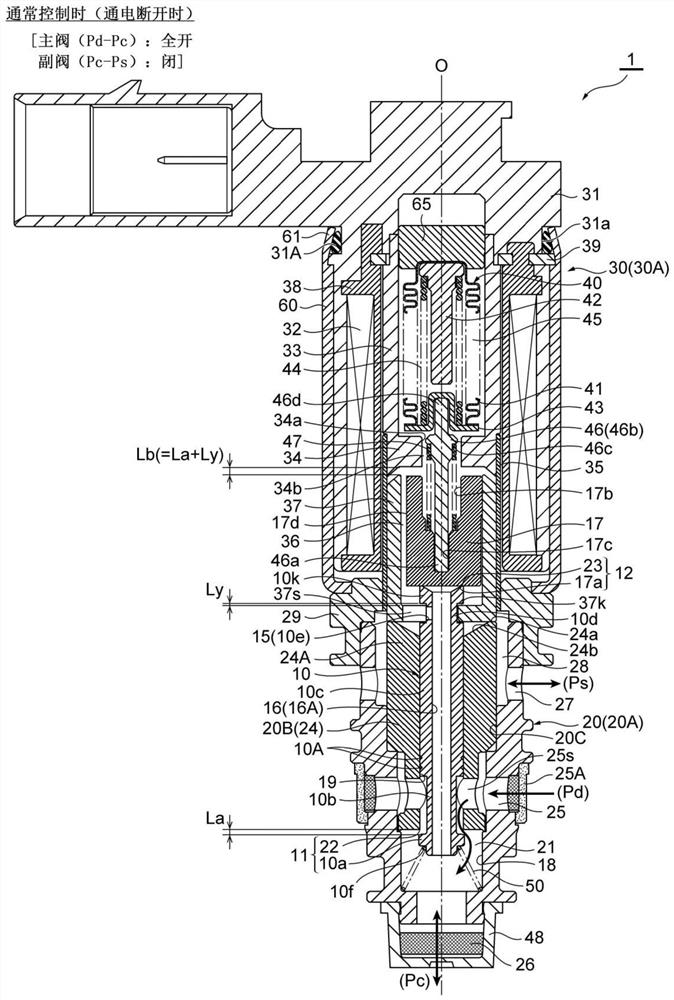
[0040] Below, while referring to the attached Figure 1 Embodiments of the present invention will be described.

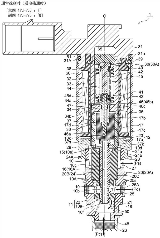
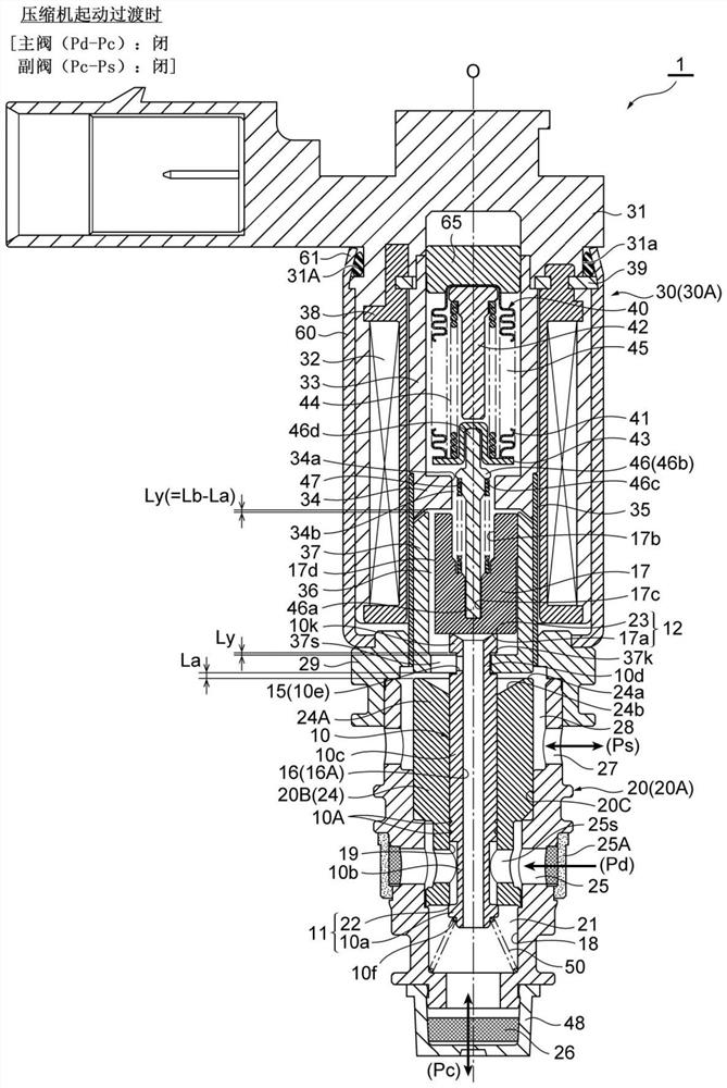
[0041] Figure 1 ~ Figure 4 It is a longitudinal sectional view showing one embodiment of the control valve for a variable displacement compressor of the present invention, figure 1 Indicates the state of main valve: fully open and auxiliary valve: closed (during normal control (when energized and disconnected)), figure 2 Indicates the state of main valve: open and auxiliary valve: closed (during normal control (when energized and turned on)), image 3 Indicates the state of main valve: closed and auxiliary valve: closed (when the compressor starts transition), Figure 4 Indicates the state of main valve: closed and auxiliary valve: open (when the compressor is started). in addition, figure 2 expressed in (relative to figure 1 ) is a state in which the valve opening of the valve port 22 (from the fully open state) is adjusted (valve opening: small state) by...


PUM


Abstract

Provided is a control valve for a variable displacement compressor, with which the effects of refrigerant pressure on a main valve body can be effectively canceled out, and it is possible to avoid structural complications and size increases in physical constitution. A pressure-equalizing passage 15 is provided for guiding pressure Pc of a crank chamber exerted on a lower end of a main valve body 10 to a pressure-sensitive chamber 45, and causing the pressure Pc of the crank chamber to be exerted on an upper end of the main valve body 10, and when current conduction to (a solenoid part 30A of)an electromagnetic actuator 30 has been turned off (when a valve port 22 is fully open), intake pressure Ps is prevented from being guided into the pressure-sensitive chamber 45 from a Ps inlet/outlet27 (a Ps in/out chamber 28), the pressure Pc of the crank chamber is guided into the pressure-sensitive chamber 45 via the pressure-equalizing passage 15, and the pressure Pc of the crank chamber isexerted on both the upper and lower ends of the main valve body 10.

Description

technical field [0001] The present invention relates to a control valve for variable capacity compressors used in automobile air conditioners, etc., and more particularly to a variable capacity compressor capable of eliminating the influence of refrigerant pressure acting on the valve core when power is turned off Use control valve. Background technique [0002] In general, a control valve for a variable displacement compressor used in an automobile air conditioner etc. introduces the discharge pressure Pd from the discharge chamber of the compressor, and adjusts the discharge pressure Pd according to the suction pressure Ps of the compressor to control the discharge pressure Pd. The pressure Pc of the crank chamber is controlled, and generally, as seen in the following Patent Document 1, etc., a valve main body having a valve chamber provided with a valve port and a Ps valve communicating with the suction chamber of the compressor is provided. An inlet and an outlet, a Pd ...

Claims


Application Information

Patent Timeline
Patent Type & Authority Applications(China)
IPC IPC(8): F04B27/18F16K31/06
CPCF04B27/18F16K31/0624F16K1/443F16K31/0686F04B27/1009F04B27/1804F04B49/22F04B2027/1831F04B2027/1845F04B2027/1859F04B2027/1854F04B2027/185F04B2027/1827F16K11/04F16K17/02F16K31/0603F05B2210/14F16K1/44F16K31/06
Inventor 伊东雅晴坂本骏田野慎太郎嶋田贤希
Owner FUJIKOKI MFG CO LTD
Why Eureka
Try Eureka