Vehicle drag reduction method and apparatus

a technology of vehicle drag reduction and apparatus, applied in the field of vehicle drag reduction methods and apparatus, can solve the problems of increasing the drag on the vehicle, slowing the boundary layer down, and reducing the kinetic energy of the vehicle, so as to increase the momentum of the boundary layer, and reduce the aerodynamic drag

Inactive Publication Date: 2010-04-15
CARLSON JAMES
View PDF34 Cites 8 Cited by
  • Summary
  • Abstract
  • Description
  • Claims
  • Application Information

AI Technical Summary

Benefits of technology

[0010]It is another aspect of the disclosed embodiment to provide for an improved turbulator (e.g., drag reducing grit tape) for reducing aerodynamic drag associated with a vehicle in motion by increasing a boundary layer momentum.
[0011]It is a further aspect of the disclosed embodiment to provide for an improved method for configuring the turbulator on the vehicle's external body surface.
[0012]The aforementioned aspects and other objectives and advantages can now be achieved as described herein. A drag reduction method and apparatus for reducing aerodynamic drag associated with a vehicle in motion by increasing momentum of a boundary layer is disclosed. Drag reducing grit tape (e.g., a turbulator) can be attached to an external surface of the vehicle (e.g., leading edge of the vehicle roof). This type of turbulator can be formed using packaging tape, glue, and grit. The packaging tape can be aligned on the vehicle roof by stretching a fiber (e.g., string, cord, strand, twine, etc) over the leading edge of the vehicle surface in order to form a straight line. A layer of a packaging tape may be aligned by the fiber and the fiber can be removed once the tape is affixed to the vehicle roof. The edges of the packaging tape may be covered with a pressure sensitive tape (e.g., masking tape) and an adhesive glue can be applied evenly over the packaging tape. A grit material can be then sprinkled on top of the adhesive after removing the masking tape and allowed to dry. The turbulator associated with the grit tape reduces the effects of the pressure drag by creating a turbule

Problems solved by technology

The slowing boundary layer loses kinetic energy and an adverse pressure gradient forms within the boundary layer, slowing it down further.
The separated flow-fields, thus, cause an increased drag on the vehicle, increased fuel consumption, and an increased level of noise perceived within the interior of the vehicle.
Such approaches, however, do not the momentum of the boundary layer with passive turbulators.
These approaches require an input of additional energy into the aerodynamic flow of air over the vehicle using energy d

Method used


Image

  • Vehicle drag reduction method and apparatus
  • Vehicle drag reduction method and apparatus
  • Vehicle drag reduction method and apparatus

Examples


Embodiment Construction

[0020]The particular values and configurations discussed in these non-limiting examples can be varied and are cited merely to illustrate at least one embodiment and are not intended to limit the scope thereof.

[0021]The disclosed embodiments may be employed to reduce drag associated with a vehicle in motion and to improve the vehicle's fuel economy. The passive drag reduction system described herein can provide a more effective and energy-efficient reduction of drag by increasing momentum of a boundary layer. The drag reduction system may be mounted on the surface of any suitable vehicle such as, for example, trucks, trailers, buses, motorized recreational vehicles, recreational trailers, cube vans, vans, mini-vans, and the like. The vehicle may be propelled by any sort of engine, such as, for example, an internal combustion engine, a natural gas powered vehicle, a fuel cell powered vehicle, a solar-powered vehicle, etc.

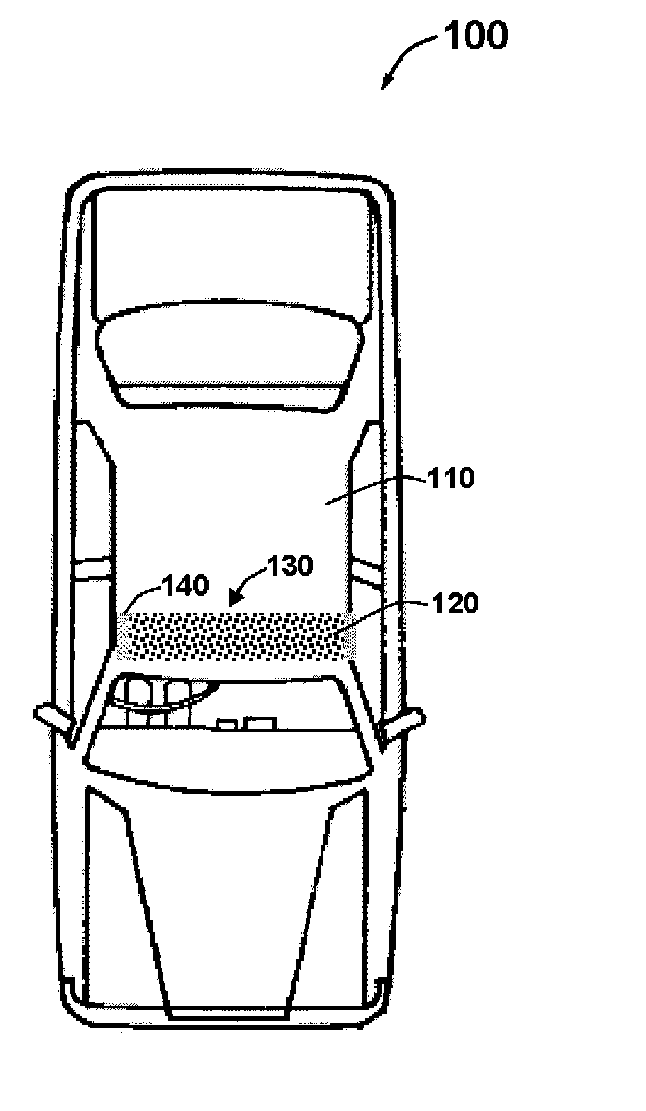
[0022]FIG. 1 illustrates a perspective view of a vehicle 100 ass...


PUM


Abstract

A drag reduction method and apparatus for reducing aerodynamic pressure drag associated with a vehicle in motion by use of grit, grit tape, or other turbulator to increase the momentum of boundary layer flow over a vehicle. A turbulator, such as grit tape, can be attached to the smooth external body surface of the vehicle to improve upon a vehicles fuel economy. The turbulator associated with the grit material reduce the effects of the pressure drag by creating a turbulent boundary layer over the surface of the vehicle that moves a separation point from a laminar flow to a turbulent flow backwards along the vehicle. The reduction in pressure drag reduces the overall energy needed to move the vehicle through the air, which improves upon the fuel economy of the vehicle.

Description

CROSS-REFERENCE TO PROVISIONAL PATENT APPLICATION[0001]This patent application claims priority under 35 U.S.C. §119(e) to U.S. Provisional Patent Application Ser. No. 61 / 104,016, entitled “Drag Reducing Tape—Grit Tape,” which was filed on Oct. 9, 2009 with the U.S. Patent & Trademark Office. U.S. Provisional Patent Application Ser. No. 61 / 104,016 is herein incorporated by reference in its entirety.TECHNICAL FIELD[0002]Embodiments are generally related to automotive vehicles. Embodiments are also related to techniques for reducing aerodynamic drag imposed on vehicles using grit tape. Embodiments are additionally related to turbulators for reducing aerodynamic drag on vehicles.BACKGROUND OF THE INVENTION[0003]Motor vehicles such as, for example, automobiles, sport utility vehicles, cars, and trucks, generally require a propulsive force in order to move the vehicle along the road and through the air. The propulsive force must overcome aerodynamic drag associated with the vehicle in ord...

Claims


Application Information

Patent Timeline
IPC IPC(8): B62D35/00
CPCB62D35/00
Inventor CARLSON, JAMES
Owner CARLSON JAMES
Why Eureka
Try Eureka