Waste gas treating device and method in dust removing room device

A technology for processing equipment and waste air, applied in mechanical equipment, separation methods, lighting and heating equipment, etc., can solve problems such as cost, and achieve the effect of saving costs and reducing the amount of fresh air

Inactive Publication Date: 2003-04-09
MW ZANDER FACILITY ENG
View PDF0 Cites 1 Cited by
  • Summary
  • Abstract
  • Description
  • Claims
  • Application Information

AI Technical Summary

Problems solved by technology

This is therefore expensive, since the sucked-in ai

Method used


Image

  • Waste gas treating device and method in dust removing room device
  • Waste gas treating device and method in dust removing room device
  • Waste gas treating device and method in dust removing room device

Examples


Embodiment Construction

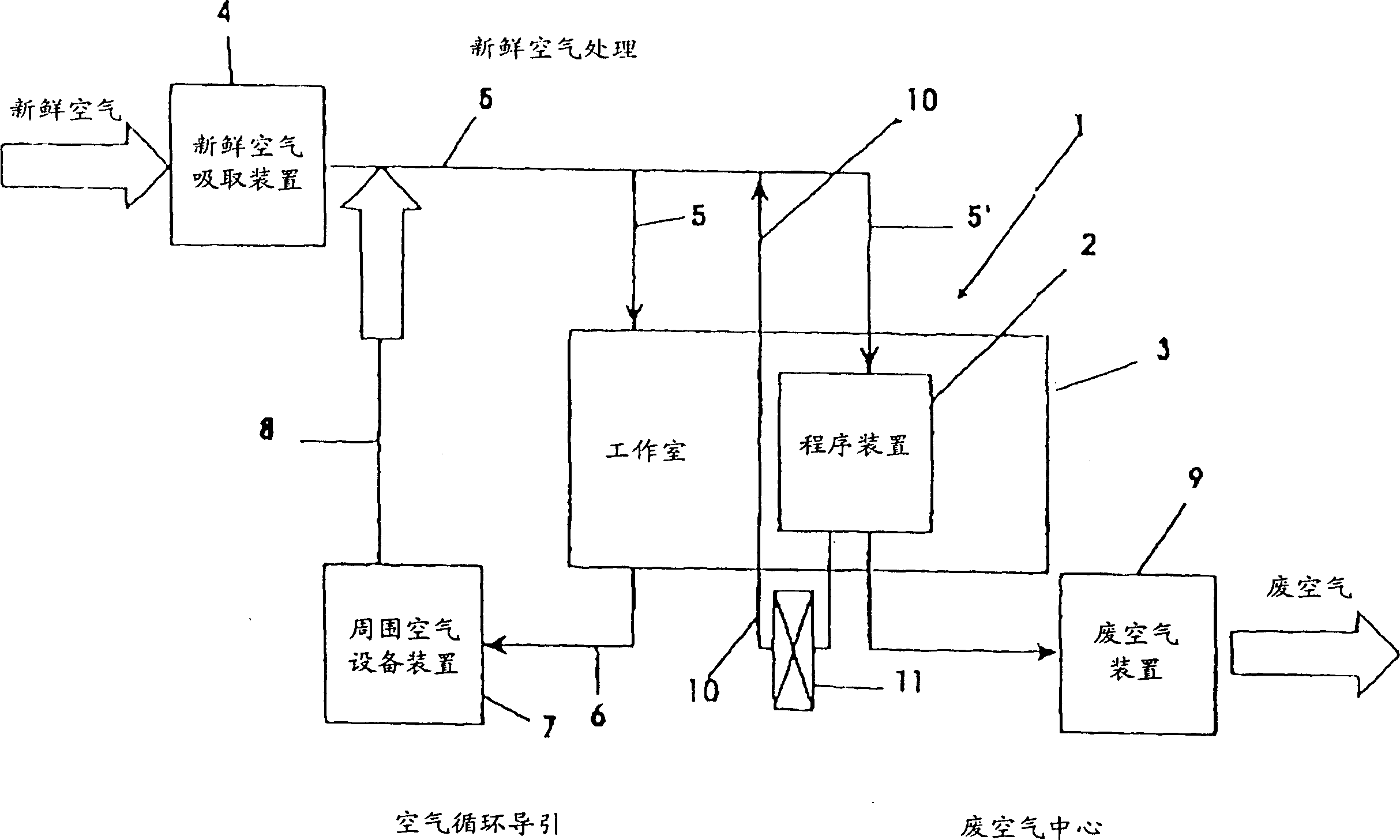
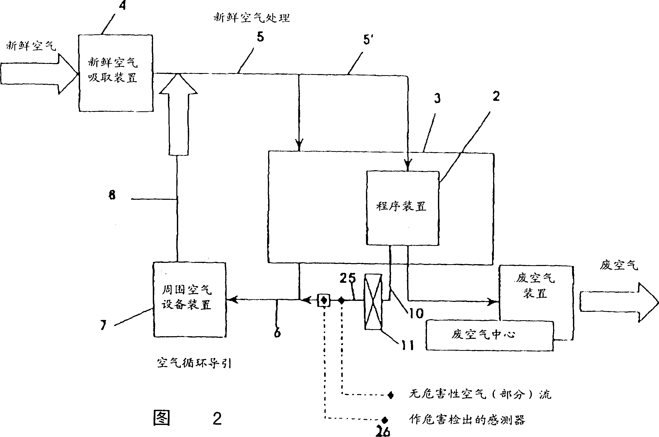
[0013] figure 1 The apparatus shown in is used to treat exhaust air from process plants 2 such as plants for wet etching, cleaning, chemical-mechanical polishing and electroplating plants used in semiconductor manufacturing. The device 1 may have only one program device 2, such as figure 1 As shown, or there may be several sequencers 2. The sequencer 2 is accommodated in a working chamber 3 , which is supplied with fresh air via at least one line 5 via a fresh air suction device 4 . The procedure device 2 also supplies the fresh space via a branch pipeline 5', and fresh air can also indirectly supply the procedure device 2 via the working chamber 3. This branch pipeline 5 ' just does not need like this. The fresh air should flow through the studio 3 from top to bottom in a laminar flow manner. The waste air leaving the working chamber 3 is separated via at least one line 6 to an ambient (circulation) air plant device 7 which sends the waste air back to the supply air line ...


PUM


Abstract

An installation, particularly in clean rooms, has a least one fresh air supply and at least one waste air device, the waste air device being connected to a work room--especially a mechanical room, a warehouse or a laboratory. At least one treatment installation is arranged in the work room. At least one supply line and at least one waste air line are connected to the treatment installation. At least one filter (11) (12) is arranged in the waste air line (10) of the treatment installation (2), and the waste air line (10) is connected to the treatment installation (2) and/or fresh air supply lines (5) (5') of the work room (3).

Description

(1) Technical field [0001] The present invention relates to a dust removal device, in particular, to a device and method for treating waste air in the dust removal device. (2) Background technology [0002] In clean room engineering, especially in the case of semiconductor manufacturing (where the semiconductor product (Fabrikat) to be processed is wet-etched, wet-cleaned and / or chemically and mechanically polished (polieren), the associated program device Located in a mechanical room or laboratory. Generally (especially when there are employees present) a minimum amount of waste air should be sucked out of this space to remove part of the heat load, reduce the concentration of harmful substances, and comply with government regulations. "Hazardous substance" in this context means the combination of corrosion, pollution and health hazards, where corrosion is related to damage to the materials of equipment, pollution is related to the possible use of The health of some employ...

Claims


Application Information

Patent Timeline
IPC IPC(8): F24F3/16
CPCF24F2003/1614F24F2003/1621F24F2003/1639F24F3/161F24F3/167F24F8/108F24F8/15F24F8/90
Inventor 马丁修特勒
Owner MW ZANDER FACILITY ENG
Why Eureka
Try Eureka