

Unit for sealing end surface of 3D helical flute with double helix angles
An end face sealing and helical groove technology, which is applied in the direction of engine sealing, engine components, mechanical equipment, etc., can solve the problems of insufficient fluid film stiffness, insufficient fluid film thickness, and unstable performance of sealing devices.
- Summary
- Abstract
- Description
- Claims
- Application Information
AI Technical Summary
Problems solved by technology
Method used
Image

Examples
Embodiment 1
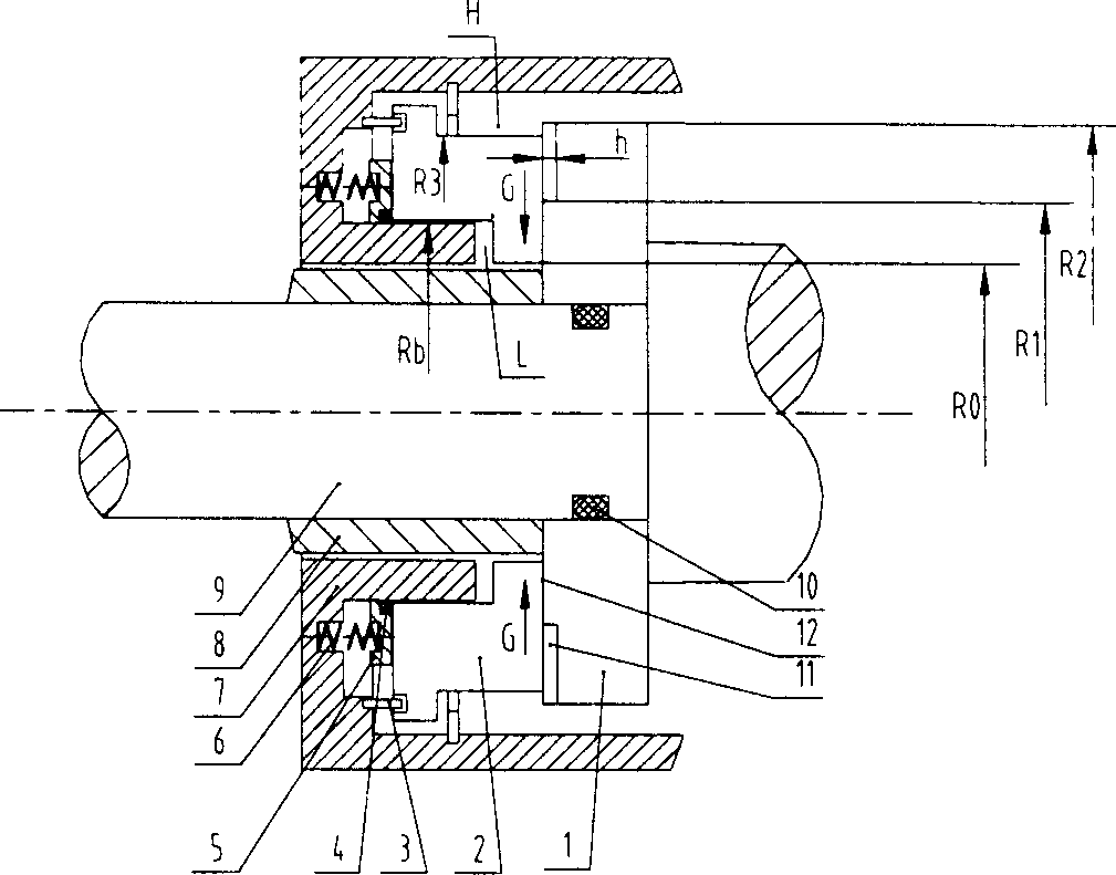
[0025] In the first embodiment figure 1 , image 3 , Figure 4 , Figure 5 The meanings of each label are as follows:
[0026] R 0 - the inner radius of the sealing face between the rotating ring and the stationary ring
[0027] R 1 - inner radius of the helical groove
[0028] R 2 - the outer radius of the helical groove
[0029] R 3 - the outer radius of the sealing face between the rotating ring and the stationary ring
[0030] R b - balance radius
[0031] h-helical groove depth
[0032] H- high pressure side, i.e. upstream
[0033] L - low pressure side, i.e. downstream
[0034] G-spiral groove pump direction
[0035] α-helix angle
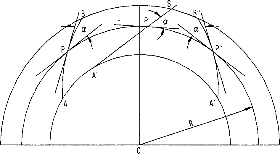
[0036] R-radius
[0037] AB, A″B″-Curve
[0038] A'B' - straight line
[0039] P, P″ - points of tangency of curves and circles
[0040] P'-point of tangency between straight line and circle
[0041] C- When the spiral groove is on the end face of the rotating ring, the direction of rotation of the rotating ring
[0042]...
Embodiment 3
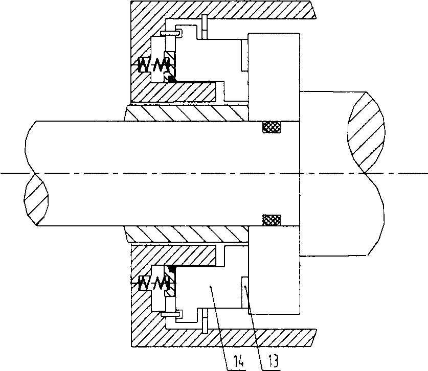
[0053] In the third embodiment Image 6 , Figure 8 , Figure 9 The meanings of each label are as follows:
[0054] R 4 - the outer radius of the sealing face between the rotating ring and the stationary ring
[0055] R 5 - the outer radius of the helical groove
[0056] R 6 - inner radius of the helical groove
[0057] R 7 - the inner radius of the sealing face between the rotating ring and the stationary ring
[0058] R b '-Balance radius
[0059] h'-helical groove depth
[0060] H'-high pressure side, i.e. upstream
[0061] L' - low pressure side, i.e. downstream
[0062] G'-spiral groove pump direction
[0063] C'-When the spiral groove is on the end face of the rotating ring, the direction of rotation of the rotating ring
[0064] M'- main groove wall profile
[0065] N'-Auxiliary groove wall profile
[0066] E'-Single helix angle helical groove auxiliary groove wall profile
[0067] alpha 1 '-Shorter main groove wall M' type line helix angle
[0068] ...
specific Embodiment approach
[0076] In order to further understand the invention content, characteristics and effects of the present invention, the following embodiments are enumerated hereby, and detailed descriptions are as follows in conjunction with the accompanying drawings:
[0077] Example 1: Please refer to figure 1 , image 3 , Figure 4 with Figure 5 .
[0078] figure 1 It is a cross-sectional view of a double-helix-angle three-dimensional helical groove end face sealing device with helical grooves arranged on a rotating ring. The sealing device includes a rotating ring 1 , a stationary ring 2 , an anti-rotation pin 3 , a secondary sealing ring 4 , a push ring 5 , a spring 6 , a casing 7 , a shaft sleeve 8 , a shaft 9 , and a static sealing ring 10 .
[0079] The sealing end surface of the rotating ring 1 and the sealing end surface of the stationary ring 2 are attached to each other, the former can rotate relative to the latter, and the bonding surface of the two is the sealing end surfac...
PUM
| Property | Measurement | Unit |
|---|---|---|
| Helix angle | aaaaa | aaaaa |
| Helix angle | aaaaa | aaaaa |
| Helix angle | aaaaa | aaaaa |
Abstract
Description
Claims
Application Information