

Method assembling blade of paper cutting machine
An assembly method and technology of a paper shredder, applied in grain processing and other directions, can solve the problems of large shredding force, reduced shredding amount, and uneven force on the cutter shaft, so as to prolong the continuous operation time, improve the shredding effect, and solve the problem of The effect of uneven stress
Inactive Publication Date: 2003-05-21
林中选
View PDF0 Cites 5 Cited by
- Summary
- Abstract
- Description
- Claims
- Application Information
AI Technical Summary
Problems solved by technology
The blade with this structure can easily squeeze the paper to the side of the cutter shaft during the continuous shredding process, resulting in uneven force on the cutter shaft, excessive shredding force, reduced shredded paper, and poor effect. shortened time
Method used
View moreImage
Smart ImageViewing Examples

Examples
Embodiment 1
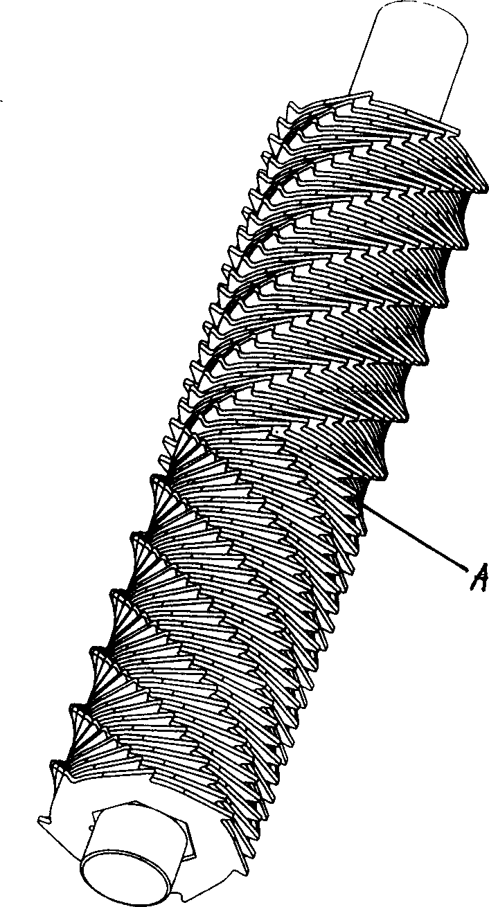
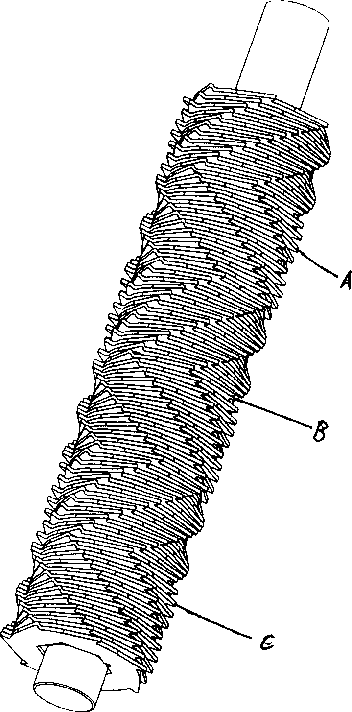
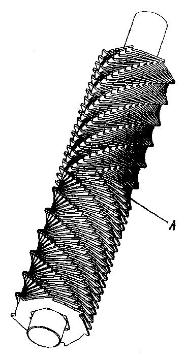
[0012] Embodiment 1. A shredder blade assembly method, including a spiral sheet body; with the center position of the cutter shaft as a boundary, the blade tips are arranged in a spiral line in both positive and negative directions on both sides.
Embodiment 2
[0013] Embodiment 2, paper shredder blade assembly method, on the basis of embodiment 1, divide according to the length of the shaft to form several interface.
Embodiment 3
[0014] Embodiment 3, the paper shredder blade assembly method, on the basis of Embodiment 1, several interfaces are formed with different positions as boundaries.
Login to View More PUM
 Abstract
The present invention relates to a blade variety of cone breaker. It includes helical blade body, the central position of cutter shaft is used as boundary, and the blade tips are respectively arranged toward two sides according to the forward and backward two-directional halical lines, this arranged blade tips can make the paper pieces simultaneously move toward two sides in the breaking process,so that it can effectively solve the problem of that the force applied on the cutter shaft is not uniform, said blade tip arrangement not only increase paper-breaking quantity, but also raise its breaking efficiency.
Description
technical field [0001] The invention relates to an assembly method of a paper shredder blade. Background technique [0002] The current shredder blades, the arrangement of their tips, including integral cutters and split cutters, all adopt a single helical arrangement. The blade with this structure can easily squeeze the paper to the side of the cutter shaft during the continuous shredding process, resulting in uneven force on the cutter shaft, excessive shredding force, reduced shredded paper, and poor effect. Time shortened. Contents of the invention [0003] The purpose of the present invention is to avoid the deficiencies in the prior art, and provide a paper shredder blade assembly method with increased paper shredding and good effect. [0004] The following technical solutions can be adopted to achieve the purpose. [0005] The paper shredder blade assembly method includes a spiral sheet body; with the center position of the cutter shaft as the boundary, the blade...
Claims
Login to View More Application Information
Patent Timeline
 IPC IPC(8): B02C18/18
Inventor林中选
Owner林中选