Virtual measuring method for determining characteristic curve of air duct for electronic equipment

Inactive Publication Date: 2003-06-11
SHANGHAI BELL
View PDF0 Cites 5 Cited by
  • Summary
  • Abstract
  • Description
  • Claims
  • Application Information

AI Technical Summary

Problems solved by technology

The geometric shape of the air duct in the electronic equipment is complex and varies greatly, so it is difficult to determine the parameters and coefficient values ​​of various places
Therefore, the calculation process is very cumbersome and takes a lot of time
[0011] In view of the above reasons,

Method used


Image

  • Virtual measuring method for determining characteristic curve of air duct for electronic equipment
  • Virtual measuring method for determining characteristic curve of air duct for electronic equipment
  • Virtual measuring method for determining characteristic curve of air duct for electronic equipment

Examples


Embodiment Construction

[0029] The following are specific implementation steps and implementation results of an embodiment in the CFD simulation software Flotherm3.1. In order to facilitate the reference comparison of implementation in the simulation software, the original expressions of some concepts in the simulation software are listed in parentheses.

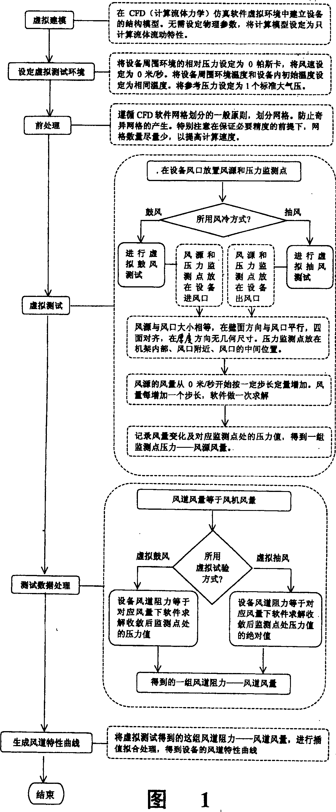
[0030] The flow chart of the implementation of the present invention is shown in Figure 1:

[0031] 1) Virtual modeling

[0032] Build the structure model of the equipment in the virtual environment of CFD (computational fluid dynamics) simulation software. Including the equipment rack and the geometric model, position and assembly relationship of each component in the rack.

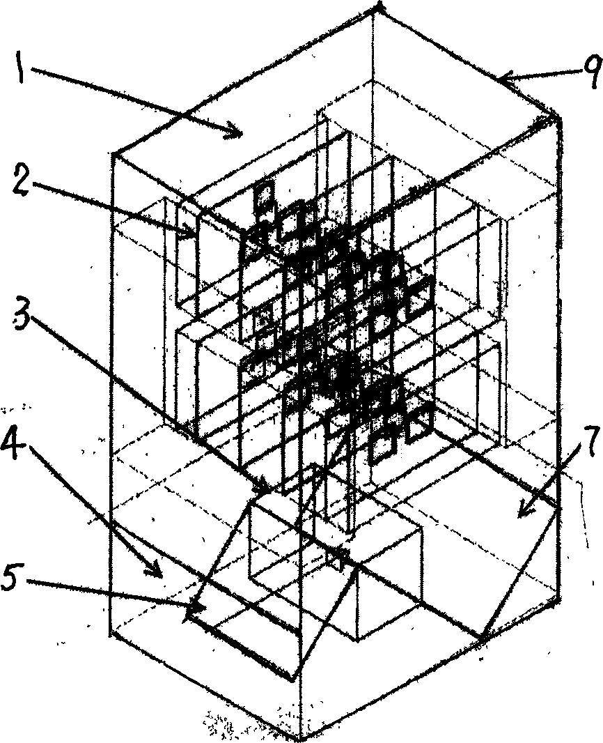
[0033] Establish the structure model of the device in the virtual environment provided by Flotherm3.1 such as figure 2 Shown. The air outlet 1 is at the top of the rack 9 and the air inlet 4 is at the bottom of the front of the rack 9. Adopt the bottom air inlet and the top air ...


PUM


Abstract

The invention is a dummy testing method of electron equipment wind way character curve, it includes following steps: dummy forming model, founds the structure model of equipment in geometry model of components, position and assembling relation; sets simulation testing environment; carries on preprocess such as grid dividing; blowing and convulsions dummy testing; testing data processing; formin wind way character curve, the tested wind way resistance and the corresponding wind quantity is interpolation processed, then gets the wind way character curve of the equipment.

Description

(1) Technical field [0001] The invention relates to a processing method for obtaining an air duct characteristic curve of an electronic device, in particular to a virtual test method for determining an air duct characteristic curve of an electronic device. (2) Background technology [0002] The existing methods for obtaining the air duct characteristic curve of electronic equipment are: [0003] 1. Test method [0004] Through the test of the prototype, several discrete air duct resistances and corresponding air duct air volumes are obtained, and then the equipment air duct characteristic curve is obtained by interpolation fitting. Obviously, the test method can only be implemented after the prototype is completed. [0005] In order to avoid the repetition of the design process, reduce design costs, and shorten the design cycle, thermal design and circuit and structural design must be carried out simultaneously. The thermal design engineer needs to determine the thermal design pl...

Claims


Application Information

Patent Timeline
IPC IPC(8): G01M9/00
Inventor 李明东
Owner SHANGHAI BELL
Why Eureka
Try Eureka