Automatic counting bar material systems

An automatic counting and bar material technology, which is applied in counting objects, counting mechanisms/items, counting of items shipped through conveying devices, etc., to achieve fast response, solve accurate counting problems, and meet real-time counting requirements.

Inactive Publication Date: 2003-06-18
UNIV OF SCI & TECH BEIJING
View PDF0 Cites 17 Cited by
  • Summary
  • Abstract
  • Description
  • Claims
  • Application Information

AI Technical Summary

Problems solved by technology

[0008] The invention provides an automatic rod counting system, which not only has the advantages of high sensitivity and fast response speed, but also can accurately count overlapping rods, thereby overcoming the shortcomings of photoelectric cell counting and manual counting, and realizing Accurate automatic bar counting

Method used


Image

  • Automatic counting bar material systems
  • Automatic counting bar material systems
  • Automatic counting bar material systems

Examples


Embodiment Construction

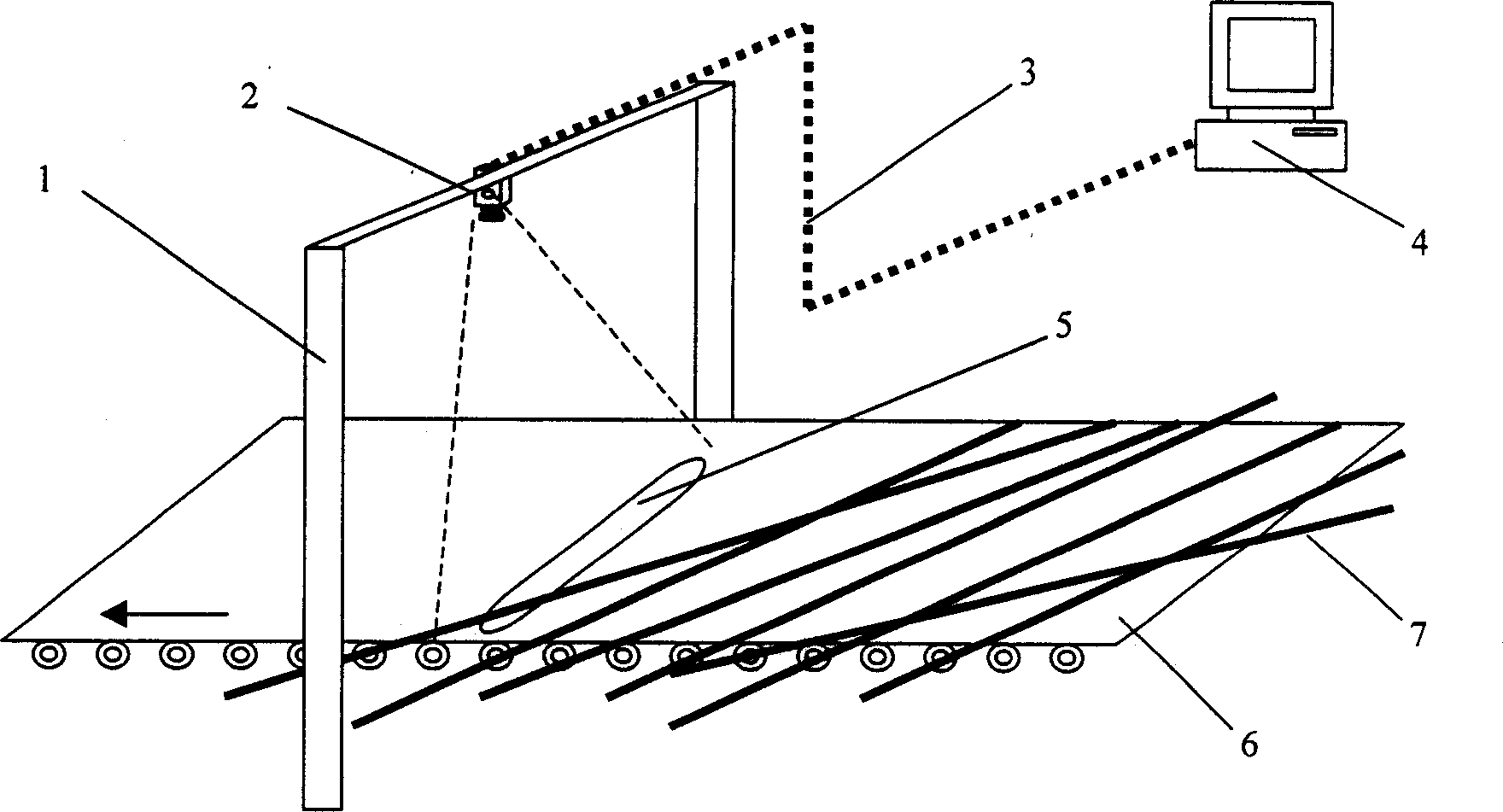
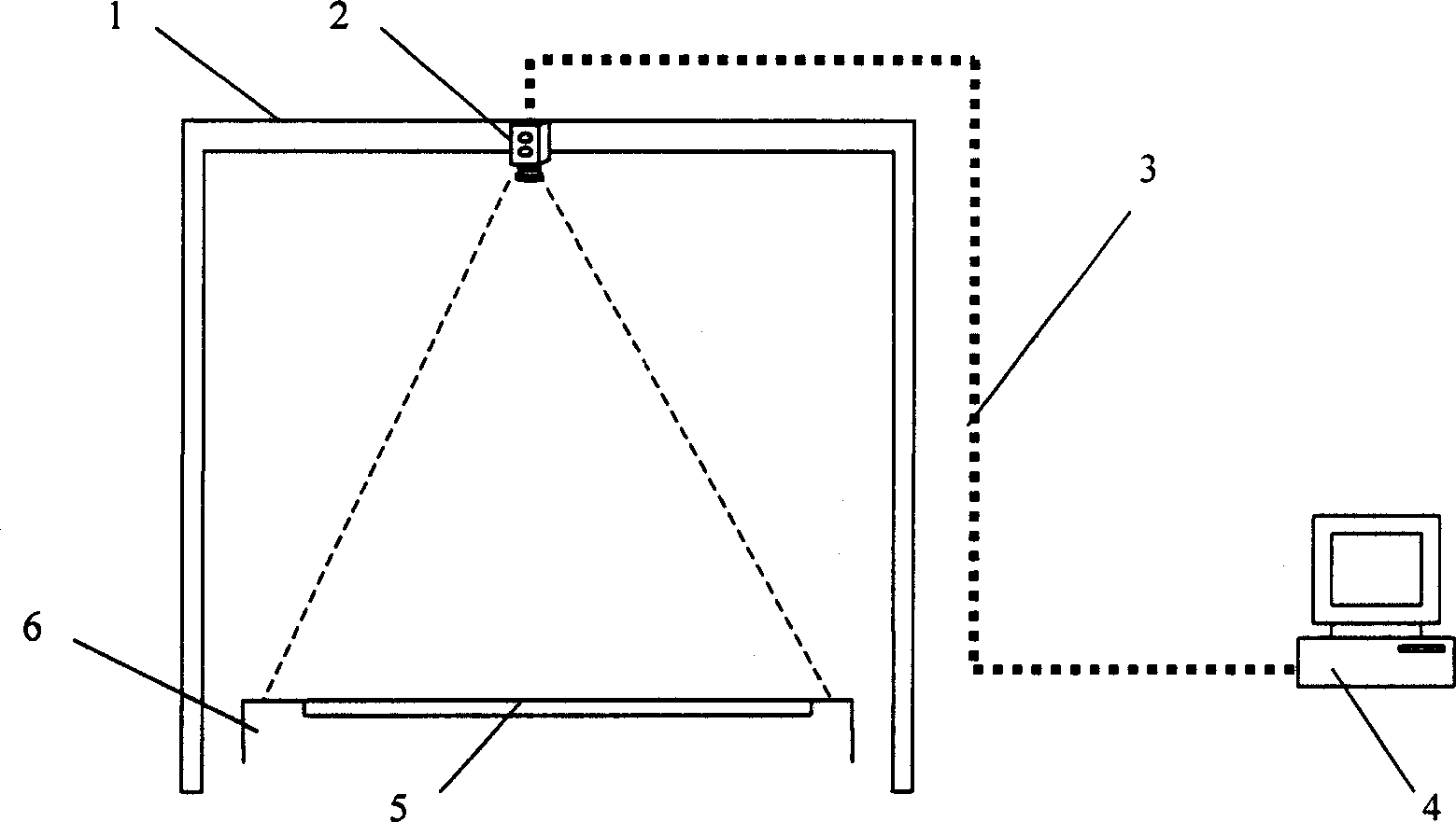
[0018] Install the system according to Figure 1 and Figure 2. First, install a stable support frame 1 across the conveyor chain 6, install a linear array CCD camera 2 on the support frame 1, install a fluorescent tube 5 at the bottom of the conveyor chain 6, and adjust the position and angle of the camera 2 so that the camera 2 and the light Tubes 5 are in the same vertical plane. The video camera is connected with the computer 4 through the data line and the control line 3 .

[0019] After the system is installed, light the lamp tube 5, and turn on the camera 2, and observe the images collected by the camera 2 through the computer 4. Adjust the position and angle of the camera 2 to ensure that the camera 2 can completely capture the light emitted by the lamp tube 5 .

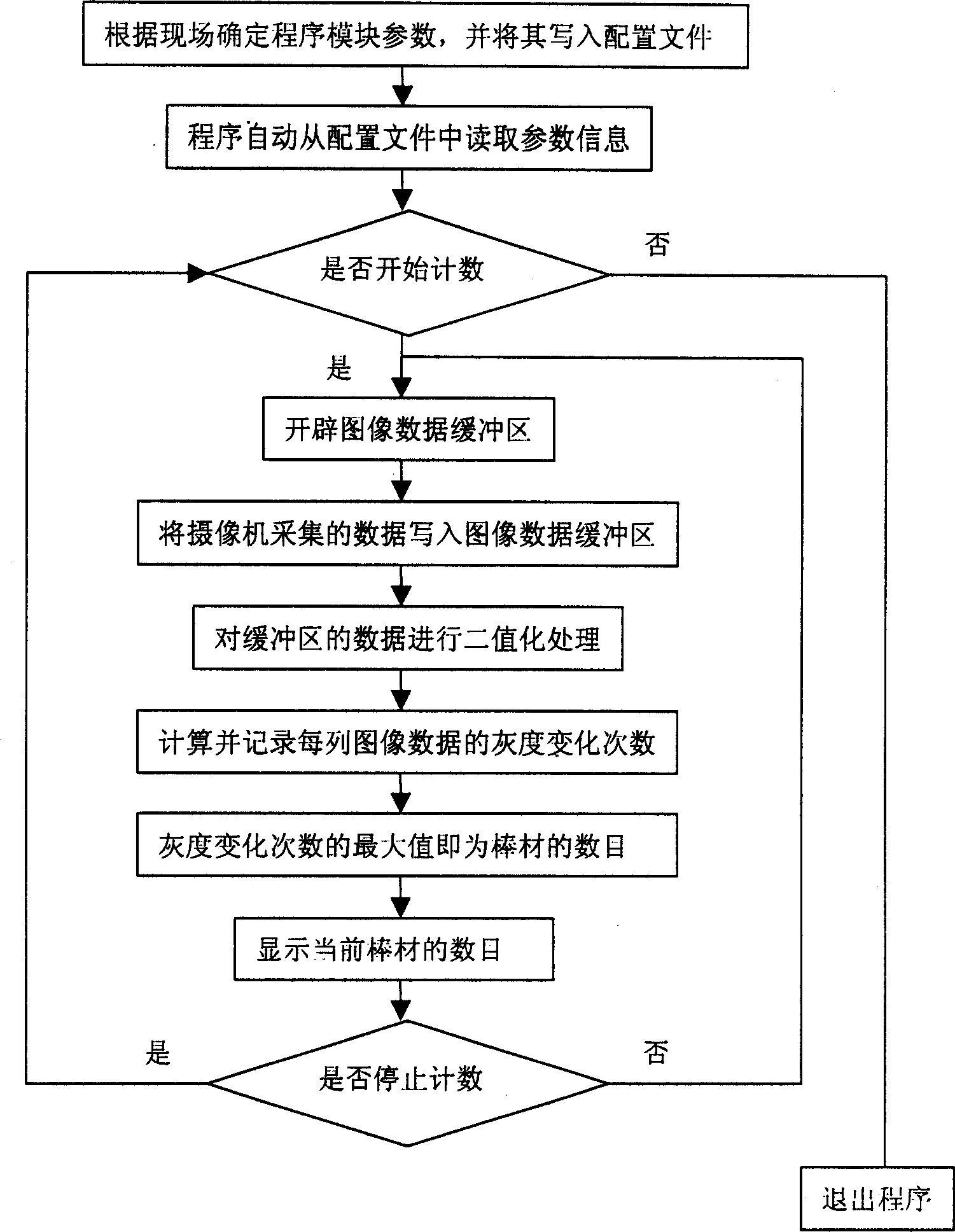
[0020] System software according to Figure three The flow chart design, the software consists of three main parts:

[0021] 1. Create an image data buffer to store the image data collected from the camera. ...


PUM


Abstract

An automatic counter system for rod material features use of linear-array CCD camera and image processing techinque. A non-strobe fluorescent lamp is vertically installed between two chains. Said CCD camera is installed above said fluorescent lamp to make them in a vertical plane. The rods pass through on the fluorescent lamp, their number can be counted according to the brightness variation.

Description

Technical field: [0001] The invention relates to the field of optical-mechanical-electrical integration, and is used in bar production lines of iron and steel enterprises. Background technique: [0002] Domestic enterprises generally adopt the method of fixed count and bundling for bars, so it is necessary to accurately count the bars before bundling. If the counting is inaccurate, it will cause huge losses to the enterprise. At present, my country's iron and steel enterprises mainly use photoelectric cells and manual methods to realize the automatic counting of bars. [0003] The photocell counting method makes full use of the photovoltaic effect of the photocell, that is, the photocell can reflect the change of the luminous flux through the change of the intensity of the photocurrent. In the field, the light source and the photoelectric tube are placed on the upper and lower sides of the rod, and the moving rod will change the luminous flux of the photoelectric tube, resu...

Claims


Application Information

Patent Timeline
Patent Type & Authority Applications(China)
IPC IPC(8): G06M7/10
Inventor 徐科
Owner UNIV OF SCI & TECH BEIJING
Why Eureka
Try Eureka