Brushless motor controller, and disk device using the same
A brushless motor and control device technology, applied in torque ripple control, recording of information on a magnetic disk, recording/reproducing by optical methods, etc. Insufficient sex, etc.
- Summary
- Abstract
- Description
- Claims
- Application Information
AI Technical Summary
Problems solved by technology
Method used
Image

Examples
Embodiment 1
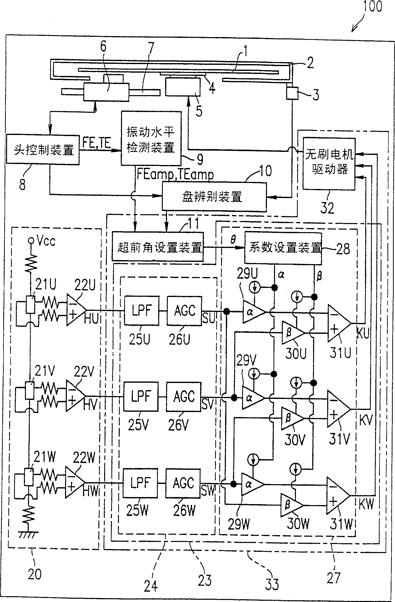
[0078] figure 1 is a schematic structural view of the disk device according to the first embodiment of the present invention. This disk device 100 allows optical disks of various recording formats to be replaceably and detachably mounted thereon by a loading mechanism (not shown). Examples of these optical disks include DVD-ROM disks with relatively high recording density (having a recording capacity of, for example, 2.6GB or 4.7GB and a thickness of 0.6mm) and DVD-ROM disks having a relatively low recording density (such as having a recording capacity of 650MB and a thickness of 1.2mm, including CD-ROM disk). These DVD-ROM discs and CD-ROM discs may be in a form not contained in the case 2, and DVD-RAM discs may be in a form contained in the case 2. Regardless of the recording format, the optical disc 1 generally has a recording track and has or allows information to be recorded along the recording track.
[0079] The disc device 100 includes a cartridge detection device ...
Embodiment 2
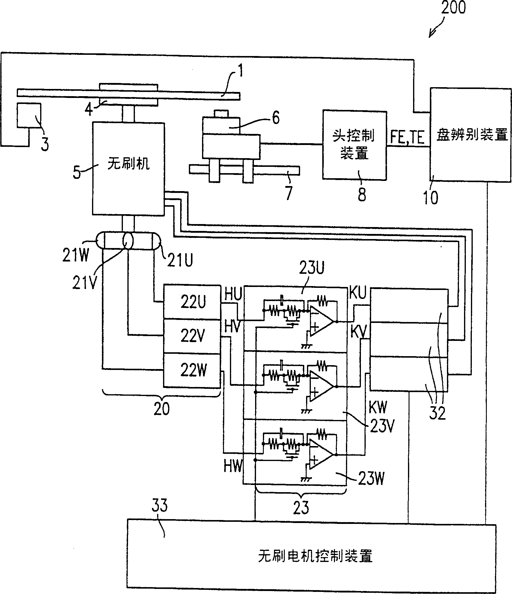
[0123] figure 2 is a schematic structural view of the disk device 200 according to the second embodiment of the present invention
[0124] The same elements as previously described are denoted by the same reference numerals. In this example, though the brushless motor 5 and the brushless motor driver 32 can be driven with a power supply voltage of 12V. The disc device 200 can reproduce information on a CD-ROM disc at a speed of x42 or higher.
[0125] Disk device 200 does not include vibration level detection means 9 ( figure 1 ), and the focus error signal FE and the tracking error signal TE output from the head control device 8 are input to the disc discrimination device 10. The discrimination result of the disk discrimination device 10 is output to the brushless motor control device 33 .
[0126] The brushless motor control means 33 controls the entire disk apparatus 200 by controlling, for example, the lead angle correction means 23 and the brushless motor driver 32 ...
Embodiment 3
[0154] Figure 4 is a schematic structural view of a disk device 300 according to the third embodiment of the present invention. The disk device 300 in this example can record information on or reproduce information from a DVD-RAM disk at a speed of x42 or higher, and reproduce information from a CD-ROM disk.
[0155] The structure of the disk device 300 in this example is basically the same as that of the disk device 200 .
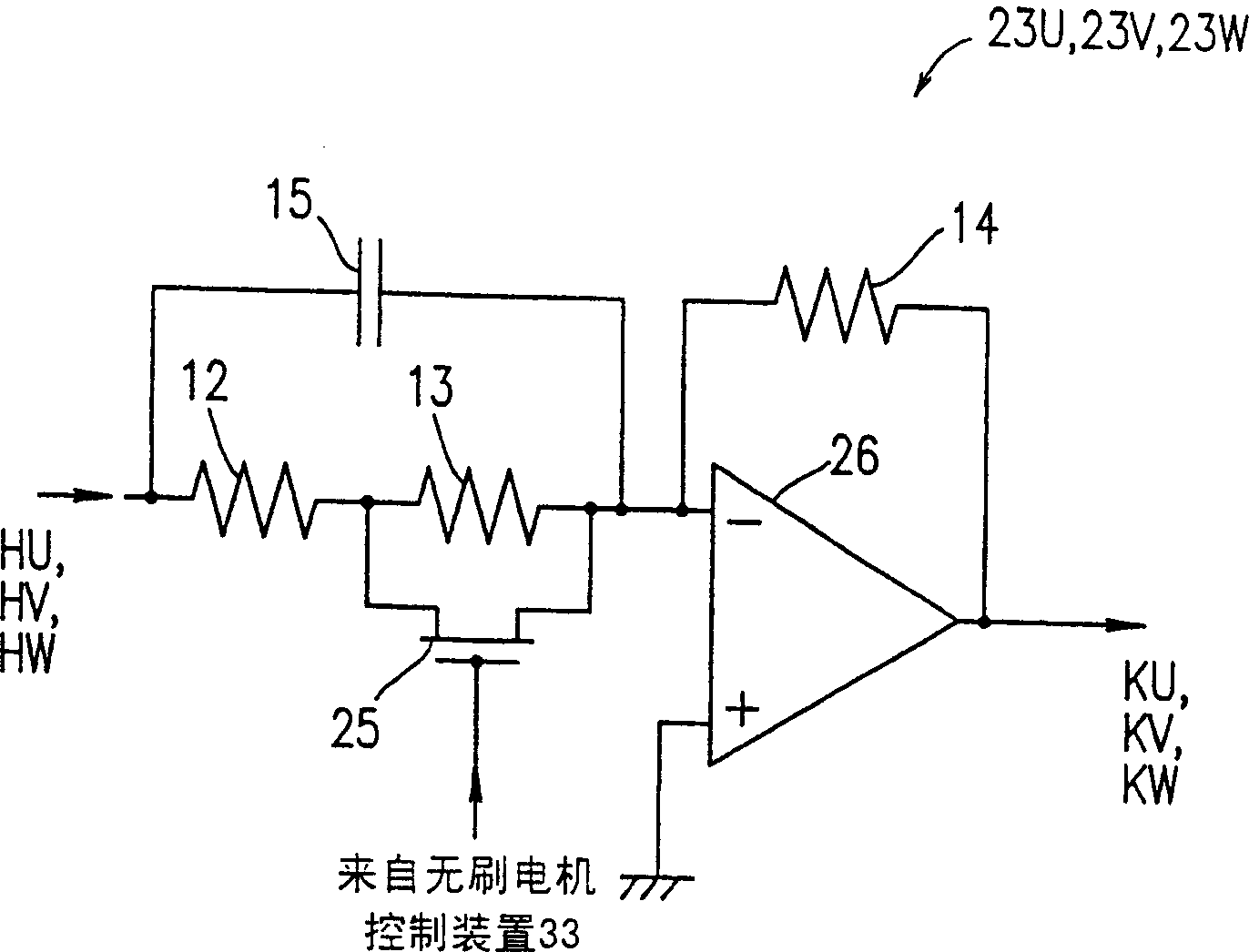
[0156] The disc device 300 differs from the disc device 200 in the lead angle correcting means 24 . The lead angle correcting means 23 in the disc device 200 includes a differentiating circuit. The lead angle correcting means 24 in the disk device 300 includes an integrating means.
[0157] refer to Figure 5 and 6 , the structure and function of the lead angle correcting device 24 will be described in detail. Figure 5 The structure of each of the phase lead angle circuits 24U, 24V, and 24W included in the lead angle correcting device 24 is shown. ...
PUM
| Property | Measurement | Unit |
|---|---|---|
| thickness | aaaaa | aaaaa |
| thickness | aaaaa | aaaaa |
Abstract
Description
Claims
Application Information
 - R&D Engineer
- R&D Manager
- IP Professional
- Industry Leading Data Capabilities
- Powerful AI technology
- Patent DNA Extraction
Browse by: Latest US Patents, China's latest patents, Technical Efficacy Thesaurus, Application Domain, Technology Topic.
© 2024 PatSnap. All rights reserved.Legal|Privacy policy|Modern Slavery Act Transparency Statement|Sitemap