Motor control apparatus

a technology of motor control and control apparatus, which is applied in the direction of motor/generator/converter stopper, electronic commutator, dynamo-electric converter control, etc., can solve the problems of limited motor drive in the weak field state, difficult to make the motor control apparatus incorporating these components smaller, and the size of the conventional motor control apparatus is often apt to be large and high in pri

Active Publication Date: 2006-01-10
III HLDG 12 LLC
View PDF9 Cites 77 Cited by
  • Summary
  • Abstract
  • Description
  • Claims
  • Application Information

AI Technical Summary

Benefits of technology

[0009]An object of the present invention is to provide a compact motor control apparatus having a compact rectifying circuit and capable of being configured with and without a position sensor. In addition, another object of the present invention is to provide a motor control apparatus capable of carrying out sensorless drive without stopping voltage application to a brushless motor even if the input voltage of the inverter circuit pulsates significantly.

Problems solved by technology

As a result, the conventional motor control apparatus is frequently apt to be large in size and high in price.
This is because motor drive in the weak field state is limited.
Hence, since the inductor and the smoothing capacitor are large components having a large inductance and a large capacitance, respectively, it is difficult to make the motor control apparatus incorporating these components smaller.
However, since the input voltage supplied to the inverter circuit pulsates in the second conventional technology, this causes a problem of stopping voltage application to the brushless motor when the input voltage is a predetermined value or less.
A problem described below occurs in the case when a sensorless motor control apparatus is tried to be built so as to be made smaller in size and lower in cost by combining the second conventional technology configured not to use any inductor and smoothing capacitor with the third conventional technology configured to carry out sensorless motor drive.
Hence, sensorless drive for the brushless motor was impossible.
In other words, in the case when the input voltage supplied to the inverter circuit pulsates, a sensorless motor control apparatus cannot be built by the simple combination of the second conventional technology and the third conventional technology.

Method used


Image

  • Motor control apparatus
  • Motor control apparatus
  • Motor control apparatus

Examples


embodiment 1

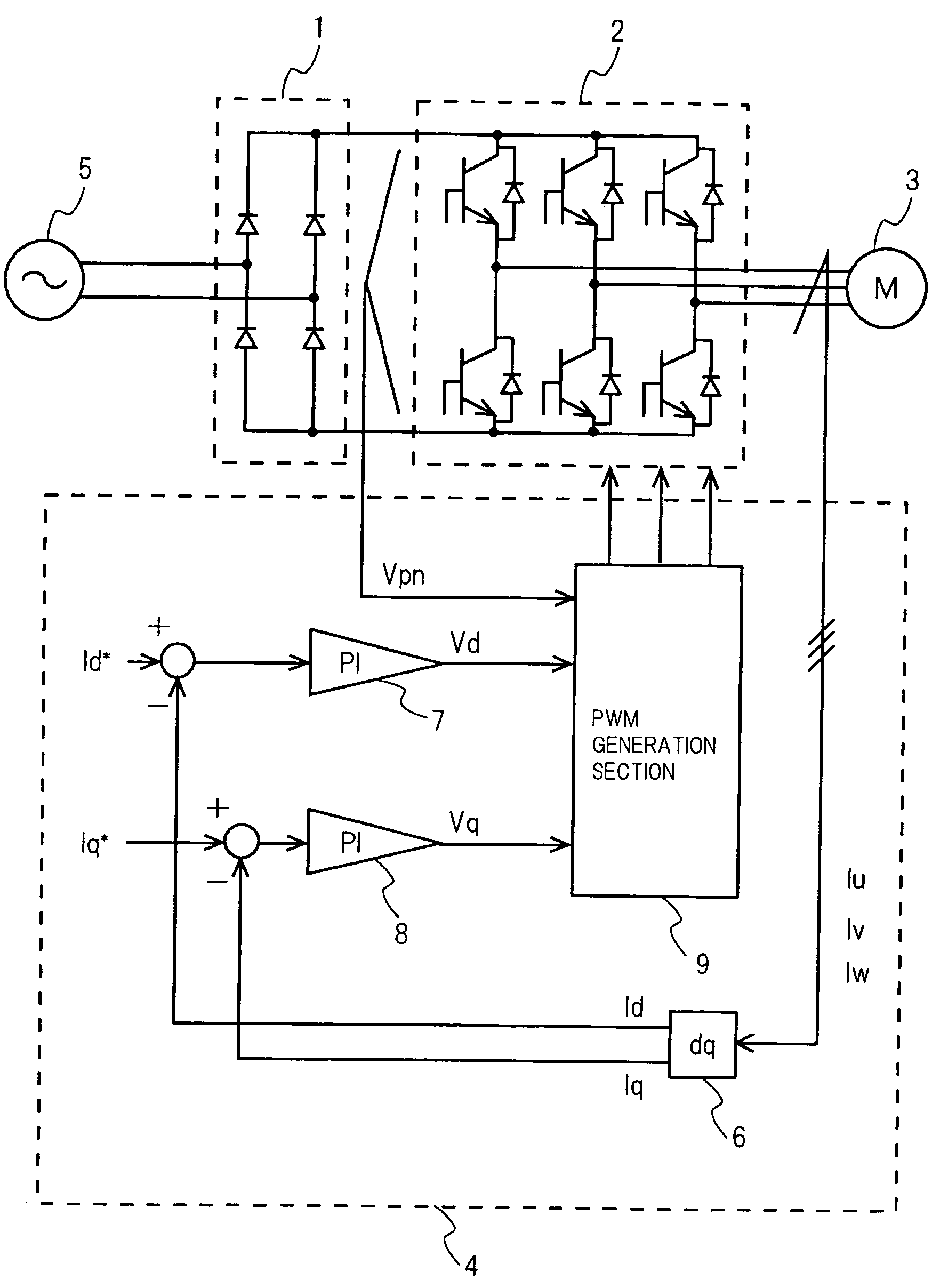
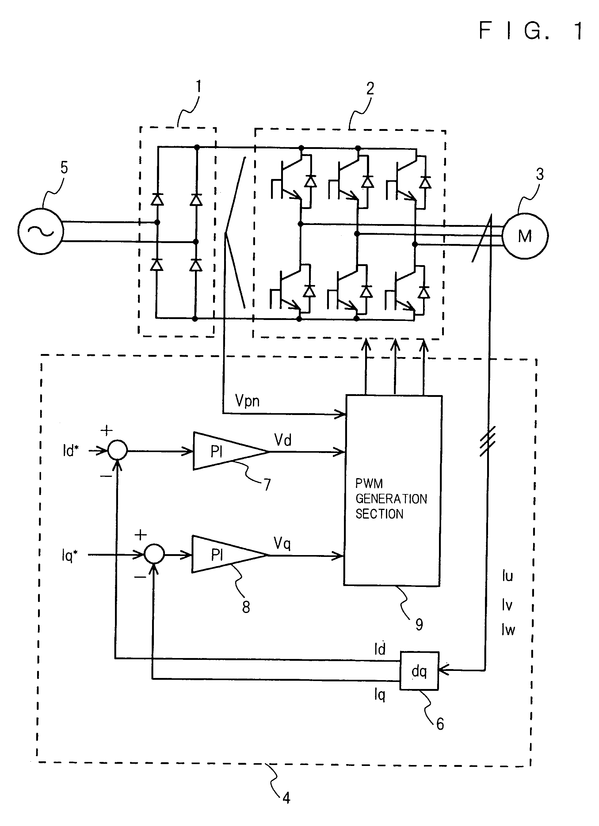
[0071]FIG. 1 is a block diagram showing the configuration of a motor control apparatus in accordance with Embodiment 1 of the present invention. In FIG. 1, the AC power output from a single-phase AC power source 5 is rectified to pulsating DC power by a rectifying circuit 1 and applied to an inverter circuit 2. The inverter circuit 2 converts the rectified DC power into an AC power and applies a desired voltage to a brushless motor 3. A control section 4 detects the current flowing to the brushless motor 3 and drives and controls the inverter circuit 2. The control section 4 comprises a dq conversion section 6, a d-axis PI controller 7, a q-axis PI controller 8, a PWM generation section 9, subtracting means, etc.

[0072]Next, the operation of the control section 4 in accordance with Embodiment 1 will be described.

[0073]The dq conversion section 6 calculates a d-axis current detection value Id and a q-axis current detection value Iq according to the following equation (1) by using the ...

embodiment 3

[0103]FIG. 8A is a graph showing the result of an experiment with respect to phase estimation by the conventional motor control apparatus. FIG. 8B is a graph showing the result of an experiment with respect to phase estimation by the motor control apparatus in accordance with Embodiment 3 of the present invention. In FIGS. 8A and 8B, the upper waveform shows the input voltage detection value Vpn, and the lower waveform shows the waveform of the estimated phase. In the experiment shown in FIG. 8A, a motor control apparatus configured by the simple combination of the above-mentioned second and third conventional technologies is used as the conventional motor control apparatus.

[0104]As shown in FIG. 8A, in the conventional motor control apparatus, the estimated phase is distorted when the input voltage detection value Vpn of the inverter circuit 2 is small, whereby the result of the estimation is deviated from the actual phase. This results in reducing motor efficiency and increasing n...

embodiment 4

[0109]FIG. 10 is a graph showing a result of an experiment with respect to the motor current in accordance with In FIG. 10, the input voltage detection value Vpn, motor current, motor current command value and motor application voltage phase are shown in this sequence from above.

[0110]When the result of the experiment shown in FIG. 10 is compared with the result of the experiment shown in FIG. 4B in accordance with the aforementioned Embodiment 1, it is found that the frequency of occurrence wherein the motor current in particular becomes larger than the motor current command value has decreased significantly. It is thus found that the error has decreased. Furthermore, it is found that the circled portion of the motor current waveform shown in FIG. 10 is closer to the motor current command value than the circled portion of the motor current waveform shown in FIG. 4B. As described above, it has been confirmed by the experiments that the motor control apparatus in accordance with Emb...


PUM


Abstract

In a motor control apparatus of the present invention, a control section which receives an input voltage to an inverter circuit, a motor current flowing to a brushless motor and a motor current command value indicating the value of a current required to flow to the inverter circuit, and controls the inverter circuit by maintaining a phase of the voltage applied to the brushless motor when the value of the input voltage to the inverter circuit is smaller than the value of a voltage required to be applied to the brushless motor.

Description

BACKGROUND OF THE INVENTION[0001]The present invention relates to a motor control apparatus for controlling brushless motors incorporated in air conditioners, refrigerators, washing machines, blowers, etc. by using an inverter circuit.[0002]FIG. 33 is a block diagram showing the configuration of a conventional motor control apparatus for driving a brushless motor. In the following descriptions, the conventional motor control apparatus shown in FIG. 33 is referred to as a first conventional technology. In FIG. 33, numeral 101 designates an AC power source, numeral 102 designates an inductor, numeral 103 designates a rectifying diode, numeral 104 designates a smoothing capacitor, numeral 106 designates an inverter circuit, numeral 107 designates a brushless motor, and numeral 108 designates a position sensor. In the case when the AC voltage supplied from the AC power source 101 is converted into a DC voltage by using the rectifying diode 103 and the smoothing capacitor 104 so that a D...

Claims


Application Information

Patent Timeline
Patent Type & Authority Patents(United States)
IPC IPC(8): H02P6/18H02P6/08H02P27/06
CPCH02P21/00H02P29/026H02P27/08H02P27/06H02M1/0085H02P6/08
Inventor NAKATA, HIDEKIUEDA, MITSUOMATSUSHIRO, HIDEOOGAWA, MASANORIKAWAJI, MITSUOSUGIMOTO, TOMOHIRO
Owner III HLDG 12 LLC
Why Eureka
Try Eureka