Electric Power Converter

a power converter and converter technology, applied in the direction of dc-ac conversion without reversal, electric devices, battery/cell propulsion, etc., can solve the problems of increasing the amount of current to be processed, deteriorating reliability, and serious automobile accidents, so as to reduce the inductance and reduce the amount of heat generated. , the effect of enhancing the reliability of the power converter

Inactive Publication Date: 2008-02-28
HITACHI LTD
View PDF6 Cites 118 Cited by
  • Summary
  • Abstract
  • Description
  • Claims
  • Application Information

AI Technical Summary

Benefits of technology

[0009]Accordingly, reducing the inductance is desired from the viewpoints of cooling the power converter efficiently and reducing the amount of heat generated. The reliability of the power converter can thus be enhanced.

Problems solved by technology

When the power converter is mounted and used in an automobile, in particular, failures in the power converter during use in a high-temperature environment or during processing of power as high as several hundreds of amperes in current level could induce serious automobile accidents.
This, however, tends to increase the amount of current to be processed.
For example, if a current of several hundreds of amperes is conducted or cut off for a short time period, since inductance will cause a voltage increase, merely shortening the switching time will result in the deterioration of reliability due to a high voltage.
For this reason, it has been difficult to shorten the switching time.

Method used


Image

  • Electric Power Converter
  • Electric Power Converter
  • Electric Power Converter

Examples


first embodiment

100>>

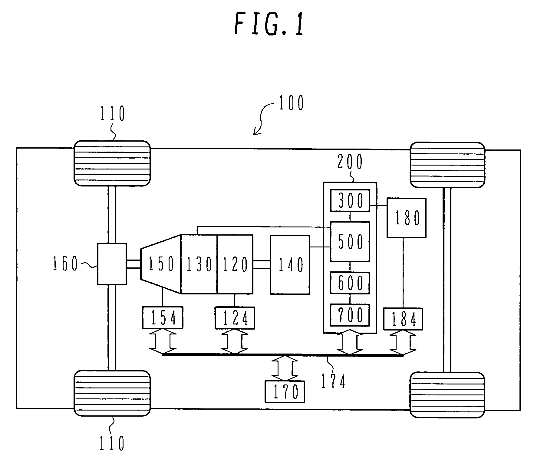
[0074]FIG. 1 is a block diagram showing an embodiment of a hybrid type electric vehicle having an electric power converter according to the present invention. The power converter 200 according to the present invention can be applied to both a pure electric vehicle and a hybrid type electric vehicle. However, hereinafter, an embodiment of the hybrid type electric vehicle is described below as a representative of both types.

[0075]The hybrid type electric vehicle 100 has an engine 120, a first rotating electric machine 130, a second rotating electric machine 140, and a battery 180 that supplies high-voltage DC power to the first rotating electric machine 130 and the second rotating electric machine 140. The vehicle 100 also has a battery to supply low-voltage DC power (14-volt power) to the control circuit described below. This battery is not shown.

[0076]Torques based on the engine 120, on the first rotating electric machine 130, and on the second rotating electric machine 140, ar...

second embodiment

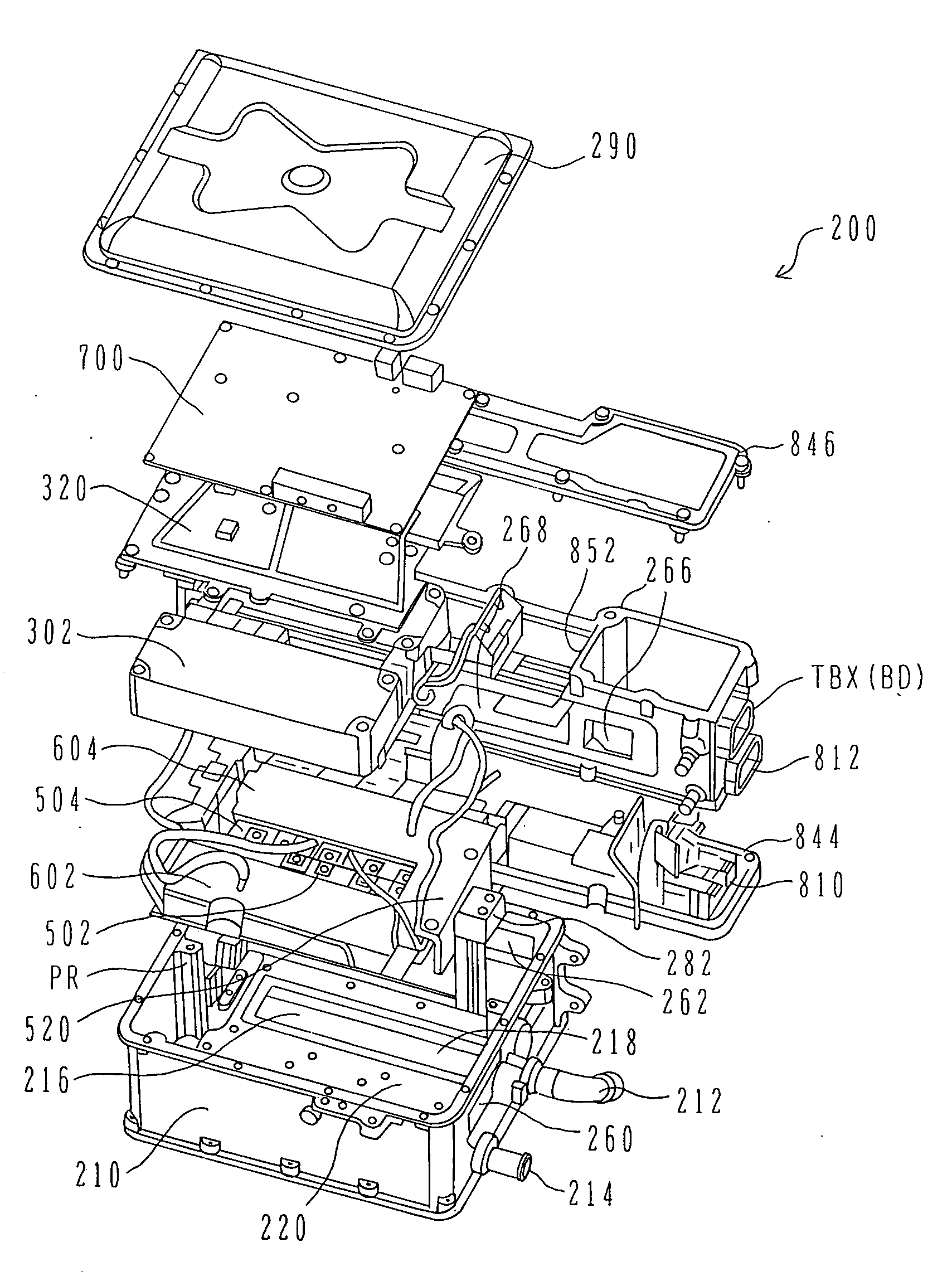
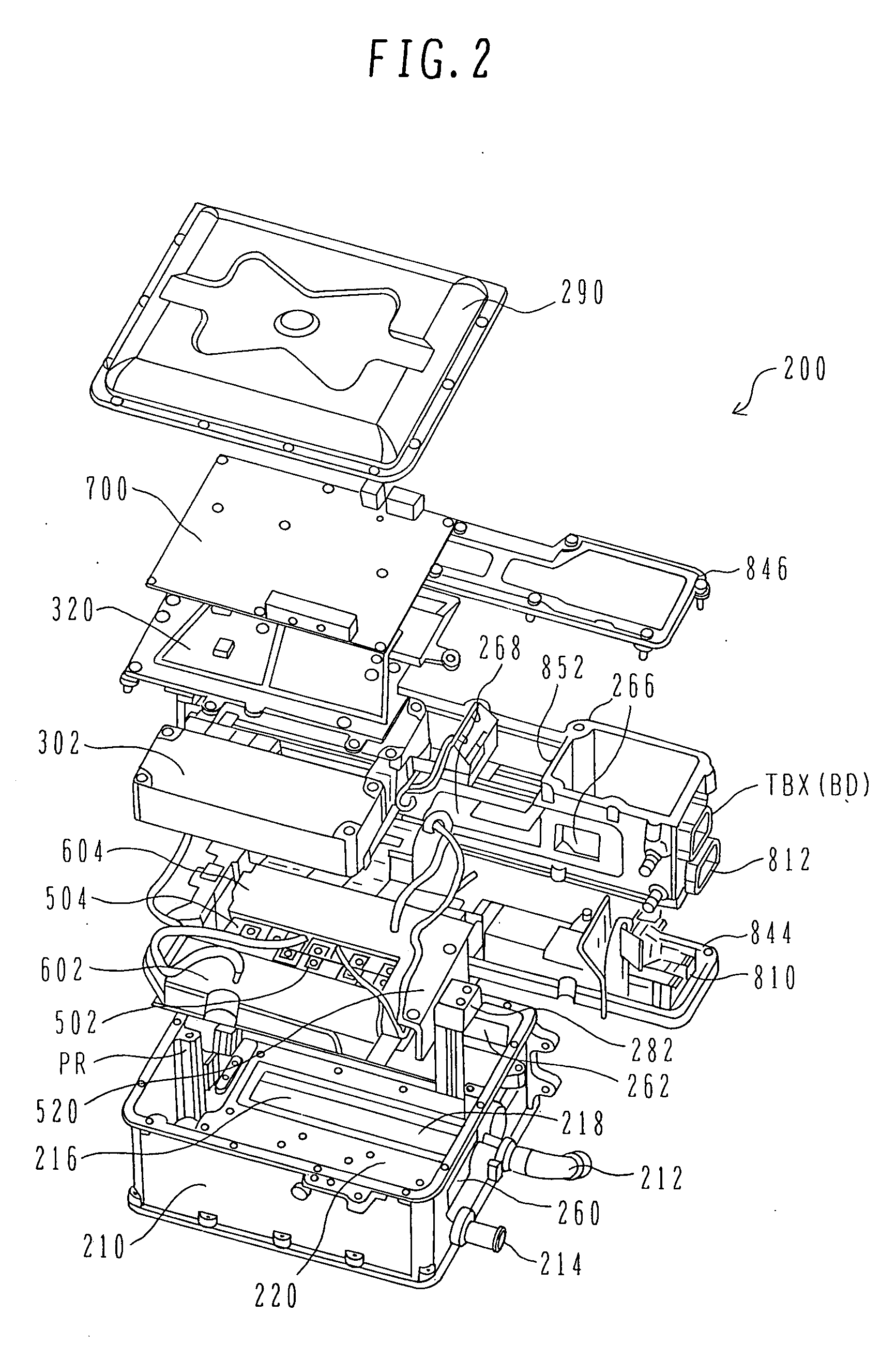
[0159]Next, a second embodiment is described below using FIGS. 23 to 28. The second embodiment is essentially the same as the first embodiment in terms of the basic concept relating to circuit composition (see FIG. 22), power module structure (see FIGS. 16 to 21), and cooling water channel structure (see FIGS. 12 to 15), and in terms of operation and advantageous effects. One difference exists in that whereas the first embodiment has cooling water channels 922 and 926 at the bottom of an inverter 200, the second embodiment has cooling water channels at a middle stage of an inverter 200. In the second embodiment, electrical components to be cooled, such as power modules 502, 504 and capacitor modules 302, 304, can be mounted on both upper and lower faces of a cooling water channel formation, and both the upper and lower faces can be used for cooling. For example, the second embodiment can be constructed so that the semiconductor modules mounted as the power modules 502, 504 on one fa...


PUM


Abstract

The present invention provides a highly reliable electric power converter reduced in parasitic inductance.
An electric power converter that includes a capacitor module which has a DC terminal, an inverter which coverts a direct current into an alternating current, and heat release fins which cool the inverter, is constructed so that: the inverter has a power module including a plurality of power semiconductor elements; the power module further has a metallic base, a dielectric substrate provided on one face of the metallic base, a power semiconductor element fixed to the dielectric substrate, and a DC terminal; the metallic base has the heat release fins on the other face; the DC terminal in the power module and the DC terminal in the capacitor module are each formed by stacking flat plate conductors via an insulator; the two positive and negative DC terminals have respective front ends bent in opposite directions; a plane including the bent sections is used as a surface for connecting the power module and the capacitor module; and the insulators overlap each other at the connection surface.

Description

BACKGROUND OF THE INVENTION[0001]1. Field of the Invention[0002]The present invention relates to an electric power converter adapted to convert direct-current power into alternating-current power, or vice versa.[0003]2. Description of the Related Art[0004]Electric power converters that supply alternating-current (AC) power to or receive AC power from a rotating electric machine operating as a motor or a power generator, may be used under severe environments. For example, when mounted in automobiles, electric power converters (hereinafter, referred to simply as power converters) may be used under severe environments such as a high-temperature environment. In addition, the power that power converters convert tends to be augmented in energy level. For example, power converters are likely to be used under the situation that a current of several hundreds of amperes flows.[0005]Techniques relating merely to reducing inductance are disclosed in JP-A Nos. 2001-268942 and 2001-332688. Also, ...

Claims


Application Information

Patent Timeline
Patent Type & Authority Applications(United States)
IPC IPC(8): H02M7/537H02M7/48H05K7/20B60L50/15
CPCB60L3/12H01L2924/30107B60L11/14B60L15/007H02M7/003H05K7/20927Y02T10/6217Y02T10/7022Y02T10/7077H01L2224/48472H01L2924/13055H01L2924/13091B60L11/123H01L2924/19107H01L2924/1305H01L2924/1306H01L24/49H01L2224/49111H01L2224/49175H01L2924/00H01L2924/00014B60L3/003B60L2210/40B60L2240/525H01L2224/48139H01L2224/4846H01L2224/49113H01L2924/14H01L24/48H01L2224/48137B60L50/61B60L50/16B60L50/60Y02T10/62Y02T10/64Y02T10/70Y02T10/72Y02T10/7072H01L2224/0603H01L2224/45099H01L2224/05599
Inventor AZUMA, KATSUNORIMORI, MUTSUHIRONAKATSU, KINYA
Owner HITACHI LTD
Why Eureka
Try Eureka